By Don Talend
Simulation of machine performance impacts various facets of industrial automation, from mechanical and electrical to controls engineering. To the controls engineer, simulation could be described as virtual prototyping that reduces a products time to market and bridges the gap between production throughput and product quality.
From the viewpoint of an interdisciplinary product design and production team, simulation often can penetrate the information silos that typically have existed between functional areas of mechanical, electrical and controls engineering. Simulation tools have a collaborative capability since anyone on the team can determine the impact of design or control changes on the manufacturing process.
Simulation tools give controls engineers opportunities to get involved in the product design process from its origin and to test machinery virtually so it becomes operational faster.
One mission-critical application uses simulation to test the interconnection of wind energy systems to municipal power grids. Energy To Quality, a wind energy electrical services company in Madrid, Spain, tests wind farms with a mobile voltage-dip generator controlled by National Instruments LabView and a PXI/SCXI system. PXI is PCI extensions for instrumentation, a PC-based platform for measurement and automation systems that operates on the PCI bus standard. The PXI/SCXI system uses high-voltage input modules to measure secondary voltages at 110 Vac while controlling relays connected to tripping coils. The program creates electrical shorts to simulate faults prior to grid interconnection. and communicates results to a remote computer. The testing procedure allows operators to know immediately if the wind turbine complies with the requirements, enabling new wind farms to come online quickly without causing outages.
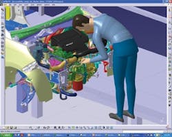
Trompeter Enterprises, Sterling Heights, Mich., an automation controls engineering firm specializing in automaking, uses Delmia Robotics, a manufacturing process simulation tool from Dassualt Systemes, to determine the positioning of welding and assembly tooling in its robotic simulations (Figure 1). A lot of times youre developing the tooling and you find out you cant get a weld done in a tight space, notes Matt Trompeter, president. Without developing it in simulation first, youre not going to find out until you get out on the floor. Trompeter says positioning problems in a process often result in the carmaker requesting a tooling change by the machine builder.
Figure 1: This digital prototyping tool allows automobile subassembly manufacturers to identify difficult-to-access areas for a robot or human before production begins on the shop floor.
(Source: Delmia)
Trompeter also uses the Delmia Quest advanced simulation tool to simulate various manufacturing scenarios with varying inputs such as facility layout, resource allocation and alternate scheduling scenarios in order to determine production throughput. It ties together robotic simulation for the robot and the simulations you get with the cycle times, combined with operator schedules and machine downtimes and gives you real throughput, he says.
Integrating Mechanical, Electrical and Controls
To Brian MacCleery, senior product manager, industrial and embedded design for design, deployment and embedded application developer National Instruments, Austin, Texas, simulation represents the biggest advancement yet in the concept of mechatronicsthe convergence of mechanical, electrical and controls engineering for more productive systems and higher-quality products. The catalyst for real progress in mechatronics, he says, is actually the replacement of mechanical controls with electronic controls.
For example, you have domains such as motion control that was almost completely controlled by the mechanical engineering team when it was gears and cams, he says. Now, the performance depends on how the PID controller is tuned, you have high-frequency drive circuits that pulse current through the motor at 20 kHz, and motion trajectories that have a huge impact on the mechanical system and the stresses, strains and torques it experiences.
Craig Therrien, product manager for 3-D CAD developer SolidWorks, explains that simulation via virtual prototyping represents an evolutionary step forward from traditional physical prototyping. By the time a physical prototype is available so the controls engineer can finalize the machine to manufacture the product under the traditional design approach, youre making panic-type fixes, adding weight to dampen vibration, slowing the throughput of your machine down so youre not having too much deflection, says Therrien. Youre doing things you really dont want to do. Youre doing a lot of extra work at the end that should have been taken care of at the front of the design.
The cause of this last-minute chaos, argues Therrien, is those information silos. Typically, you see a divide between controls people and mechanical systems designers, he notes. Usually theyll meet once at the start of the project and then they kind of go their own way. A lot of times near the end, the machine designers throw their designs at the controls guys and say, Make it work.
In recent years, NI has worked with SolidWorks to use and co-develop several simulation tools to eliminate machine and product design problems early in the development process. MacCleery recently wrote a white paper detailing the use of these tools, which will be used in a machine design guide NI is publishing. These simulation tools are designed to facilitate a system-level approach to development known as graphical system design.
In late 80s to early 90s, fuel controls were the big thing for jet engines, MacCleery says. The push was to go from mechanical fuel controls dependent on fuel pressure and temperature readings to electric fuel control systems. Now you see it moving into other industries as well.
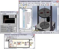
A machine-control application for graphical system design has high stakes, too. MacCleery cites an example of a machine equipped with a rotating coupling or shaft with some flexibility that can experience bending. A laser-etching machine fitting that profile was the subject of a presentation MacCleery gave during NIs user conference in 2007. (Watch this presentation, Prototype with LabVIEW Real-Time Module). He demonstrated how LabView and SolidWorks can be integrated into a predictive simulation model that automatically calculates inertia resulting from the use of certain materials in a product. In this case, the steel in pliers to be etched could be entered as a database variable, with fields to enter product materials and dynamic operating data such as acceleration (Figure 2). MacCleery demonstrated how the values affected the oscillation in a rotating shaft that connects the etching disk and another disk equipped with a motor and belt drive on the etching machine. According to MacCleery, the laser-etching example shows how controls engineers can use simulation tools to program logic for supervisory-level machine operation but also perform detailed design that includes the digital control logic, timing/sequencing and motion profiles. They can perform motion trajectory design using high-level function blocks that represent straight-line, arc and contour moves or even advanced techniques such as electronic gearing and camming.
Figure 2: CAD software is integrated with another application for a digital prototype of a laser-etching machine that will etch pairs of pliers.
(Source: National Instruments)
Simon Bosley, Inventor product manager, points out that the programs dynamic simulation capability digitally prototypes a component, and incorporates actual operating conditions.
Typically, a 3D assembly is frictionless and weightless, says Bosley. You add physics, then you can run the simulation, and Inventor calculates the accelerations, velocities, all those kinematic properties. One of the major paybacks for a mechanical engineer is that it calculates FEA stresses for you.
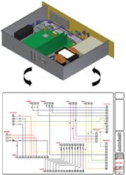
Figure 3: This program allows the integration of an electrical wiring schematic with a 3D CAD model to identify areas for wiring deployment without the need for a physical prototype.
(Source: Autodesk)
One time-saving feature of AutoCAD Electrical, says Mark Burnard, an electrical engineer with dairy and food-processing machinery manufacturer Osgood in Oldsmar, Fla., is an archiving capability that allows him to revisit the evolution of past designs when he is working on a new digital prototype. Thats very useful as far as seeing past revisions and transitions up to the current actual drawings, says Burnard. In our best productivity, we produce a machine a week. It does certainly save a lot of time. People can access drawings at the same time.
Mechanical engineers have a tool in Inventor, electrical engineers have AutoCAD Electrical, and they can work on their own or together. Change management is very important, Jose Santos, AutoCAD Electrical product manager says. They have full control of their own functions, but they can transfer the data back and forth and leverage the data each one creates.
The simulation capabilities of these tools can facilitate controls optimization, says Bosley. For industrial machinery, a lot of the work is about continual improvement: How can we make the machine go 20% faster? Also, you might be over-engineering, but by making a few changes and really understanding everything, you could specify a smaller actuator or motor.
Tim Webb, director of marketing communications for Simulia, Dassault Systemes component and subsystem simulation tool, says controls engineers can identify problems using Simulias FEA capabilities. We look at ways to connect the control system and the finite element analysis, says Webb. One company we work for is studying robotic arm vibrations, trying to understand what component causes vibration at high speeds. Is it the bolt? Is it the connection? What component do they need to stiffen? Thats where finite element analysis comes into play by looking at the components in your manufacturing line to determine fatigue, vibration, stress, that sort of thing. Were enabling people to evaluate the material levels of their components as well.
Simulias Abaqus Unified FEA product suite is designed to allow integration among various physical simulations such as loading, vibration, impacts and thermal coupling. By using your common technologies and methods, you can simulate a common model and common practices among your engineers, says Webb. You can perform a linear analysis, a non-linear analysis, a durability analysis and a thermal analysis using a common model, and youre not waiting for one engineer to do an analysis in one package, translate those results to somebody whos doing it in another package and try to make them come together. Youre actually able to do these analyses using the same model and some of them sequentially.
More simulation prior to physical prototyping can save a significant amount of time and money, argues Webb. Sometimes machine builders say, If it breaks, Ill just fix it. If they did spend a little more time and resources on simulation, they might be able to avoid some downtime.
Bigger-Picture Simulation
Networking hardware for a process doesnt necessarily have to wait until physical equipment is available either. Phoenix Contact launched a control platform called nanoLine that uses a modular programmable logic controller equipped with a few I/O points that can perform simple control tasks. A nanoNavigator programming tool downloadable from the companys website is used to simulate a hardware configuration via a flowchart. What were simulating is PLC programming, says Jeff Pinegar, product manager, automation, Americas business unit for Phoenix Contact. You want to get the logic right before you hook up hardware. Additionally, he says, the controls engineer might decide one day that a hardware component is needed and simulate the use of that component within the flowchart while the actual component is shipped. With the simulator, you could download the software right now, write your program, debug your program and be ready to put it in the software when it arrives, says Pinegar. The tool allows simulation of wiring schemes and verification that wiring and components are correct while components are being delivered, reducing the amount of physical system testing that would otherwise be necessary once hardware is available.
Sponsored Recommendations

Leaders relevant to this article:

