Mechatronics is really nothing new. Combining mechanical and electrical engineering methods, tools, designs and components has been done for several decades at least. Automation, control and software elements have been mixed into mechatronics projects for many years. So what else is new?
Jim Montague is the Executive Editor of Control. Jim has spent the last 13 years as an editor and brings a wealth of automation and controls knowledge to the position.
Well, even though mechatronics has been around for a while, few users had the funding and computing power needed to gather and analyze enough data to make mechatronics practical at their design and build stages. And, even if they had enough resources, most mechatronic modeling tools didn't include enough physical, dynamic data to produce useful representations that could help design engineers and builders make better decisions. Many builders argue it's still better to build and test physical prototypes because eventually they will have to do it anyway.
What's happening lately is that mechatronics is getting simpler, easier, affordable and practical for everyone. However, it still requires users to make some significant mental shifts, such as truly cooperating with other engineering disciplines and considering how their specialties affect overall systems.
"Mechatronics can be as simple as an automatic urinal flusher or garage door opener, or it can be as complex as the Mars rovers or the Cassini probe, which are really just giant mechatronics platforms," says Kris Jentzsch, project engineer at Pacific Gas & Electric's Diablo Canyon Power Plant (DCPP), who has B.S. and M.S. degrees in mechatronics. "In the U.S. Navy and nuclear industry, we refer to mechatronics as instrumentation and control."
The Bigger Picture
Apparently, where and how the word "mechatronics" is used isn't as important as how much collaboration it can achieve. For instance, Jentzsch reports that he's been working with students at Cal Poly to build a training skid with two tanks, one heater, transfer lines, valves, sensors and other components. However, their initial proposals were written separately, and didn't include many of the interdisciplinary bits and pieces the skid was going to need, such as drain valves for low-flow areas, load calculations for breakers, chemicals needed to control corrosion, and other basic issues.
"This happens because the mechanical side says it doesn't do electronics, and the electrical side says it doesn't do mechanics," Jentzsch explains. "So the mechanical side doesn't consider the temperature sensors the skid will need, while the electrical side buys the RTDs, but doesn't consider how to mount them. However, mechatronics means working together more, putting in different components, and seeing what they do to the whole system. We're still trying to get the skid built, but we haven't resolved all these issues yet."
John Pritchard, global marketing manager for motion control and design at Rockwell Automation, adds, "Our litmus test for mechatronics asks: When mechanical designers are deciding what to do and specify, are they really considering the impact on the electronics and controls, and vice versa?"
Profiles Add Dynamic Motion
No doubt the biggest advance in mechatronics recently is the addition of sophisticated and dynamic motion data to its formerly static CAD/CAE designs and performance profiles, which better reflect the reality of how machines operate.
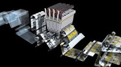
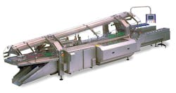
For example, engineers at Kliklok-Woodman in the U.S. and U.K. recently needed to design and add a more durable flap kicker to their company's high-speed Celox end-load cartoner and sealer (Figure 1). The kicker deflects open the flaps of each carton, so packaged foods can be smoothly loaded into the cartons. However, the kicker, driven by pneumatic cylinders, tended to wear down more quickly at high speeds, and one food manufacturer needed to run at a very fast 325 cartons per minute. So Kliklok's engineers began working on a servo-driven kicker, and used Rockwell Automation's Motion Analyzer modeling and simulation software to identify and digitally test motion solutions with the right speed and throughput. Motion Analyzer recently was tied to Dassault Systèmes' SolidWorks 3D mechanical CAD software via an application programming interface (API) that provides a live link between them.
"It made complete sense to use Motion Analyzer to do the initial motor sizing because the motion of the flap kicker is solely dependent on size of the particular carton and its flaps," says Florin Bruda, Kliklok's mechanical engineer. "I could plug in the specific end-user requirements, quickly test different servo motor sizes to find the right one, and avoid testing each option on a physical prototype."
To do this, the engineers created motion profiles of the servo-driven kicker in Motion Analyzer, and transferred them to SolidWorks to visualize the machine's movement. Next, SolidWorks calculated the torque and force required to move the load through its profile, and Motion Analyzer used the results to size and select the right motors and drives. The engineers estimate they reduced design time by about a third by using Motion Analyzer and SolidWorks together.
National Instruments has worked with Dassault for several years to integrate NI's motion control design tools based on its LabView and SoftMotion software with SolidWorks' mechanical simulation capabilities.
Common Language and Culture
One of the surest ways to combine mechanical, electrical and controls engineering more easily and more affordably for more users is to push them to use the same language and software, which then drives understanding and cooperation.
For instance, the Centre for Concepts in Mechatronics (CCM) in Eindhoven, the Netherlands, builds and integrates production line equipment for use in the semiconductor, image and printing, and pharmaceutical industries. The center employs mechatronics principles to work with partners and on its own to develop new machines and equipment. For the medical industry, CCM recently worked with Philips to develop a digital pathology scanner that captures images of slides and distributes them digitally, and independently developed its MuScan microscanner that filters fluids through a micro sieve, as well as a long-function measurement instrument to help diagnose asthma.
"Mechatronics only covers mechanics and electronics, so we prefer the term 'multi-physics' because this field involves other disciplines," says Arend-Jan Beltman, CCM's mechatronics manager and CTO. Beltman explains that CCM's projects always begin with an application's needs. In the case of the MuScan and the long-function instrument, this meant working closely with the applications lab at Utrecht University's academic and research hospital. CCM then gathered its project manager, physics and software experts and others to consider how to combine technologies, and design a solution. They picked a piezo-acoustic sensor and software for the long-function device, and then worked with a consortium, including Thoromed, which built the instrument; the hospital, which tested it; and a design firm. CCM produced the software, mechanical design and integration. "The team even settled on a type of micro-filter for MuScan that someone had seen a beer brewer use at a tradeshow," Beltman adds.
Combine, Simplify Controls
Though mechatronics is most closely associated with design, several users and suppliers also employ its basic principles to simplify formerly complex control arrangements. They report that thinking mechatronically enables them to combine previously separate sensing, instrumentation and control signals and functions into one device, which can help optimize basic operations and help troubleshooting, too.
"The biggest challenge in mechatronics is to accept that it's a new method for all the different parties, and that it's a shared responsibility between multiple engineers from different disciplines," says Christian Fritz, senior product manager for advanced machine control and robotics at National Instruments. "But it's worth it. If you manage to successfully implement a mechatronics approach, everyone's job will become easier. Instead of implementing workarounds, you'll be able to really focus on the optimal design and create systems that work together perfectly."
Symbiosis Stimulates Simulation
Just as give-and-take between engineering disciplines aids mechatronic design and machine building, these model-based designs and tools are returning the favor to the engineers.
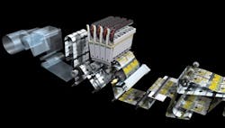
For instance, to help printing press builder Agfa improve the repeatability of its :Dotrix Modular industrial inkjet printer and its 2 ft wide, 24 m/min color images, CCM recently combined its Smart and fleXible Control Solutions (SAXCS) and Simulink Real-Time Workshop and xPC Target model-based design tools from MathWorks to create a custom substrate controller (Figure 2). The print-encoder roll on the inkjet printer typically carries 225 kg rolls of paper and triggers its inkjet heads to fire droplets from about 4 ft onto the paper substrate. But tension on the paper can cause stretching or slight misalignment of the droplets, and can reduce precision. These substrate carriers use steel belts, and must often maintain an accuracy of ±5 µm over a 750 mm area.
Figure 2: The substrate path of Agfa's :Dotrix Modular industrial inkjet printer gained precision and repeatability by isolating slightly inaccurate force-control parameters, simulating non-linear dynamics, and redeploying more refined substrate controls that were developed by the Centre for Concepts in Mechatronics and tested with MathWorks tools.
Agfa
Operators couldn't tune the printer's force-control parameters to compensate enough, so CCM's engineers isolated these variations in substrate forces, and began tuning three control loops that exhibited coupling by using Simulink to model the non-linear dynamics of the substrate path. Next, they developed new controls with CCM's controller design tools and Control System Toolbox, and simulated and refined the controls for the three loops to minimize unwanted loop interactions and improve precision. Also, after simulating the new controls in Simulink, CCM used Real-Time Workshop to automatically generate C code for the controller, test it on a real-time prototype using dSpace hardware, and use Signal Processing Toolbox to analyze measured data. Finally, they tested the custom controls on a physical prototype machine, re-refined the design in Simulink, and generated new code. They also used xPC Target and its embedded option to deploy the real-time embedded controls on PC hardware for production use on the printer, which allowed validation without retranslating the code by hand.
"It can take a lot of time to convert a control architecture to software because the design must be communicated to programmers who are not machine dynamics experts," Beltman says. "Simulink and our SAXCS approach let us realize our implementations directly, which reduced costs and saved up to four weeks. Not only does automatic code generation save a great deal of time, but we can simply change the model to update our design, and we know it will be implemented as required. Our design iterations, from making changes to hardware testing, are completed in five minutes. We improved our functional performance by a factor of five."
Continue Reading

Leaders relevant to this article:
