How design software impacts development time, predictive modeling and thermal management
Electrical design software has changed the way we build. Our panel of industry veterans discusses shortened development times, predictive modeling, thermal management in the cabinet and how to select software based on the application.
Meet the panel
Keith Marler, design manager, Concept Systems, a system integrator with offices in Oregon, North Carolina, Colorado and Washington.
Pascal Flambard, CEO of IGE+XAO North America.
Victor Alvarez, senior manager, applications marketing, Bentley.
Thomas Yip, CEO, Radica Software.
Sean-Patrick Mulherrin, Electric P8 product manager, ePlan.
Marcel Schulz, application consultant for control panel engineering and CAx data & tools, Siemens.
Johannes Rumpler, head of presales information, Siemens.
How is electrical design software reducing the time from machine concept to delivery?
Marler: Electrical design software now has the ability to automate the design-to-build process in several areas, ultimately reducing the time from concept to delivery.
First, some CAD packages are now database-driven. This means information can be entered once and is available across all users in the same platform in real time. This includes symbols, part models and other component information that need to be accessed each time a part is used in a new design. The up-front development cost can be heavy, but the information control and reusability is far superior to previous, manually managed methods.
Second, 3D layouts can be created directly from information obtained during the schematic design process. This eliminates some duplicate entries, reduces errors in design and opens the door to using time-saving features inherent to 3D design.
Third, control panels can be more efficiently manufactured with information that can now be exported directly from the design. Wire and device numbers can be exported directly to label machines. Drill patterns and hole cutouts, created from component information, can be ported directly from the 3D layouts to machine code, allowing control panels and enclosures to be machined instead of manually fabricated.
Mulherrin: One of the most critical aspects of electrical design is data consistency and data management from the concept of a machine until the commissioning, service and maintenance of that machine. Nowadays, companies use various software tools to capture the data during the engineering process. For historical, price or convenience reasons, CAD packages are often used to display the data graphically; however, all the engineering data is often captured in tables using Excel or basic database systems such as Access, for example. A constant synchronization between the graphical representation and the data representation of the engineering task is required. This synchronization is often a manual process. Any modifications need to be made in both environments and affect various disciplines. The modifications need to be made many times entering the same data.
Typically, the electrical design has implications in various disciplines such as process engineering, where electrical sensors and actuators are used to control processes and are represented in the process flow diagram (PFD) or process & instrumentation diagram (P&ID). Electrical design is also involved in fluid power engineering where controlling cylinders and valves are performed using electrical actuators and sensors.
Providing engineers and designers software to capture electrical design data early on in the engineering process is crucial. Using the design software, this data can then be made available throughout the engineering process to reduce data redundancy and minimize costly errors through multiple entry of the same data.
Also read: ECAD: simple or complex?
Electrical design software should also provide the infrastructure for standardization. Many engineering processes are based on copy-and-paste. Previous design are copied from various sources and used for new designs. These designs are manually adapted to the requirements and many errors are made during the process.
Standardization also provides the basis for repeatability and error-free and high-quality design. This is also a fundamental requirement for design automation, which will drastically reduce the design time and thereby the costs.
Flambard: When taking the opportunity to switch from electrical drafting to a real electrical CAD system, the resulting time saving is clearly on the documentation phase of the electrical project—BOM production, terminal strip layout, wiring lists. By experience, the breakdown of distribution schematics and documentation is roughly 50/50. This documentation phase can be reduced by 90%, and the schematic phase can be shortened by about 20%, so a global saving of 50% is absolutely realistic. Using an electrical CAD package helps to standardize designs and produce very professional project reports.
Schulz: With a CAE system, you can plan an application on the computer. On the one hand you can do the electrical engineering very fast and on the other hand efficient changes and optimizations. It also helps to avoid fundamental mistakes. For example, an automatic test can find wrong potential allocations in plan. More complex applications often require different views for one function. The CAE software ensures the correct and unique assignment of all equipment used in the whole project.
Alvarez: Electrical design software has been around since 1990 and has made significant strides starting from basic drawing simplification and error checking to complete project delivery and interfacing to PLC and HMI technology. Today’s products have the capability to start at project conceptual design and prototyping, as well as quoting and budgeting to final drawing creation total project reporting via automation tools. In addition, revision tracking and iterative process design is included. Some products, such as Bentley’s Promis.e application, even include full 3D capabilities for visualization and interference detection.
Yip: From concept to delivery, the processes involved would surely include cost estimates, electrical/pneumatic/hydraulic circuit designs, procurement, machine building, final delivery and after sales.
In the case of our electrical design software called Electra, users can simply drop predesigned circuits onto a drawing and be able to generate the bill of materials (BOM) for quick cost estimates.
During actual circuit design, built-in automation typically allow users to complete circuit diagrams three to five times faster, with tools like tagging, cross-referencing, generating terminal blocks, panel layout and reusing circuits. For Electra, all these powerful tools apply to electrical, pneumatic and hydraulic circuits.
Once the circuit design is completed, a BOM can be generated and passed to procurement where they can be converted to request for quotations and purchase orders easily, quickly and without errors.
When building the machine itself, diagrams produced by electrical design software are typically more accurate and contain cross-referencing that is normally not included in manual designs with far less errors. This allows machines to be built much faster with fewer communication problems between the designer and builder.
For final delivery and commissioning, engineering changes can be quickly updated to conform to safety and operational standards. Even during after-sales services, problems and debugging can be easily identified much faster, resulting in a far better customer experience.
In summary, electrical design software allows an engineer to spend more time with customers, solving problems and improving bottom lines, rather than being bogged down with the nitty-gritty detail of documenting circuit diagrams.
How can electrical design software be used for predictive modeling to lower prototyping costs?
Alvarez: By using tools such as template manager or auto project building, prototyping can be simplified, and fewer iterations are required. Integrating this with 3D can save even additional time and money.
Rumpler: By using a CAE system, the user always creates a virtual prototype of the control cabinet. You can find and eliminate problems in a very early stage, and this guarantees high planning reliability and avoids time delays in later project phases. Identifying problems with wiring and assembling in front of the building process is only one example for this.
Flambard: Producing an accurate panel layout automatically out of schematic allows electrical engineers to select the right panel size upfront. And interfacing with a mechanical 3D CAD system allows a very accurate simulation of cable paths. Sizing cables and harness space reservation using a 3D virtual mock-up drops significantly the number of physical prototypes.
Mulherrin: Electrical design software stores the data used for the design. It can provide all that data required for virtual validation of enclosures where space requirements and collision situation can be fixed before the prototyping phase. Additionally data can be extracted for the benefits of simulation. Typically, this data has to be entered manually by the person creating the simulation environment. Now it can be imported.
Electrical design software also can manage and provide heat dissipation values for calculating cooling requirements and minimizing costs due to non-failure of electrical equipment during the prototyping phase because of heat. Providing correct wire length information in electrical design software will also minimize cost by minimizing the purchasing of wires and cables for the prototype.
At what stage in development should electrical design software be used to simulate conditions that impact design and build?
Mulherrin: Electrical design software should be used at all stages in the development process. Different data may be captured during different phases of the development process. Early on, major electrical components can be captured and sized and purchased to optimized delivery times. Cable length can be calculated easily and accurately to minimize waste. And electrical design software can also provide a lot of data required by the software developer automatically such as I/O or description data so there is no need for manually reentering the data. The electrical design software can also automatically provide all the necessary documentation for building the system such as 2D layouts, wiring lists, bill of materials and terminal strip layouts.
Alvarez: Electrical design software should be used right from the beginning. By doing so, there is a direct impact on design and build by being able to view the various models. By using proper tools, efficiencies can be gained prior to construction.
Schulz: For developing a product, it is always best to use software that allows integrated work throughout all project phases. A seamless information flow is one of the most important success factors. Software is optimized for its purpose and usually can simulate characteristics at a very early stage. The sooner the simulation functions are used, the better the product and its production can be optimized.
Flambard: For complex designs, collaboration between mechanical engineering teams and electrical engineering teams must start as early as possible including pre-design phases. Regular 3D mock-up data exchange allows converging to a final design, constantly refining both sides of the project. This is, in fact, the definition of an ECAD solution. A good integration of electrical CAD and mechanical CAD applications allows companies to select best-of-breed products from different vendors.
What sorts of applications are best-suited to a simple, stand-alone electrical software, and which applications require programs that are integrated into CAD software, so electrical design and CAD mechanical design can be performed in parallel in an electrical CAD (ECAD) package?
Marler: Applications that simply require schematics to be created, modified or reproduced would be good candidates for stand-alone electrical software packages. Examples might be field control retrofits, updating existing drawing packages or creating documentation for pre-existing control systems.
Concept Systems exclusively uses electrical platforms that are integrated with mechanical CAD software. The applications that benefit the most from these integrated packages are design-to-build systems with one or many control enclosures that are being manufactured in our facility. There is an even greater benefit when we are producing a complete system or many systems as the OEM. This allows us to create design packages that have component reference links throughout the system, such as field devices that wire back to control enclosures. Linking these components within the same platform eliminates the need to manually create references.
Yip: Stand-alone electrical design software is best-suited for projects that have a low production run or require customization, while integrated CAD packages are mostly suited for high production run that does not involves too much changes.
Rumpler: To answer this question you have to look at the complexity of the application and to the customer’s requirements. For designing a simple unique control cabinet, it can be beneficial to use a simple stand-alone solution while more complex applications like production lines, roll conveyor or presses needs a parallel CAD and CAE engineering in most cases. Changes of the electrical engineering often affect the design of a product or its production. By using an integrated solution, changes resulting from other adjustments can be done relatively comfortably and quickly.
Mulherrin: Only a subset of the data found in the CAD packages is used for electrical design. If the CAD application can provide a list of all the sensors and actuator for any given system or machine, then the design software should be able to import that data and use it as a basis for creating the control for that system or machine. This means that a complete integration of electrical and mechanical design is not necessary. A simple management of the delta between the mechanical design and the electrical design at any user-defined time is all that is necessary. The electrical design software should provide functionality to easily import component lists and validate that list against the current design. Any changes in the electrical design should also be exported to the CAD package so that any change in the mechanical aspect of the modified component is made in the mechanical model.
Alvarez: Given today’s market demands and requirements, this is no longer an option, rather a requirement. Mechanical, electrical and 3D must be integrated for maximum benefit. By utilizing common data models and tools such as i-models, these efficiencies can easily be achieved and are a reality today.
Flambard: IGE+XAO identified three different needs and accordingly developed three families of electrical CAD applications.
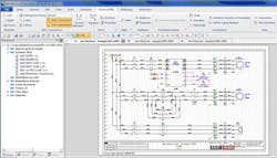
Figure 1: A 3D panel module allows composing with a schematic tool for panel builders’ specific needs and no need to train electrical designers on a full mechanical CAD package.
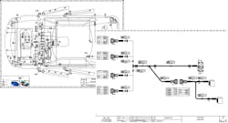
The SEE Electrical product range is extremely simple to use with a learning cycle as short as a few hours and dedicated to electricity and automation specialists for electric , pneumatic, hydraulic and others. The recent addition of a 3D panel module allows composing with a simple and powerful schematic tool for panel builders’ specific needs and no need to train electrical designers on a full mechanical CAD package as they would only use a few functions (Figure 1).The SEE Electrical Expert product range is an extremely customizable electrical CAD application that can meet the needs of the most demanding automation designers and also allows them to produce from the most basic designs to the most complicated aerospace harnesses (Figure 2).
Figure 2: Customizable electrical CAD applications can meet the needs of the most demanding automation designers.
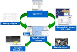
The SEE Electrical PLM family is based on the functionality of SEE Electrical Expert for the 2D schematic part but extended to harness design fully interfaced with Dassault Systeme 3D Catia Mechanical package. Product developments are parallelized with common check points and converge on a final product that fills both electrical and mechanical requirements (Figure 3).
Figure 3: Product developments can be parallelized with common check points and converge on a final product that fills both electrical and mechanical requirements.
With panel space becoming tighter and the need for more efficient cooling technology, how can electrical design software help with thermal management of the cabinet?
Schulz: With a CAE system you plan and design the complete electrification of an application and, last but not least, the design and organization of the control cabinet. The software should be able to deal and calculate with thermal data such as environmental temperatures or power loss data. But the fundamental elements are the data from the supplier. This is where, for example, product dimensions and power loss data come into play. Only if the data is available does the software gets enabled to do exact thermal calculations. In this case, the software can find problems and partially do automatic corrections and suggestions. For example, it could do automatic derating or visualize hot spots. And all this will be done before the first part will be assembled.
Alvarez: It seems no matter where one is in the world, space for electrical equipment is becoming a premium. A proper ECAD solution needs to have the ability to include thermal energy requirements for its parts catalog and content. By having this information the most efficient cabinet can be used. 3D visualization can help with this requirement and be further analyzed using CFD to simulate heating and cooling flows in limited space to validate designs.
Yip: Most electrical software design software would be able to export data and allow thermal analysis when required.
Marler: When 3D layouts are created, flow modeling and thermal analysis can be used to optimize layouts, improving heat dissipation.
Mulherrin: By laying out all the components required for the automation system in an enclosure system, various calculations and visualization effects can be performed by the electrical design software to determine the total power dissipation of the components in the enclosure, as well as providing a graphical visualization of the heat zones of individual components and enclosures. Based on that information, the electrical designer can organize the position of his components around the enclosure for maximum cooling efficiency. The cooling unit can also be sized correctly and placed in a position where the cooling will have an optimum effect on the components inside the enclosure.
Flambard: Electrical design software allows simulating accurately the thermal impact of every single component inside a cabinet, as well as their combined effect. Knowing that, it becomes way easier to optimize cabinet sizes and component distribution or placement into them. IGE+XAO 3D cabinet design can perform this kind of analysis and allows live simulation of component placement for a better optimization of the ensemble.


