As a long-time controls engineer whose main focus is battling the march of time when it comes to technology, the ever-evolving field of communications has been a welcome addition to the arsenal of tools at my disposal.
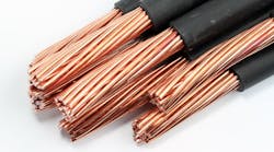
It seems like the early days of control design were eaten up not with the actual circuit design but with the more involved planning of how to physically get the wires from the main enclosures to the various satellite enclosures needed to deploy the system on the machine or process.
For those who have enjoyed any tenure in this fascinating career, the bane of the older version of a control system wasn’t necessarily in the original installation/commissioning of the control system, but in the troubleshooting of it, years down the road, when something starts acting up.
While some things do happen at startup, like skinned wires in a conduit, the real challenge happens when insulation starts to break down or moisture gets into a conduit and corrodes things just enough to create partial grounds or impact the dielectric strength of the insulation on the conductors or other similar issues.
The previous example covers just the intra-enclosure challenges, but communications has also had a major impact on the connections inside each enclosure. Early control systems needed hard-wired signals for every function on every component in the panel.
For example, a variable-frequency drive needed individual wires for stop, run, forward, reverse, jog, accelerate and decelerate, to list just a few functions. An analog signal for speed might also be involved.
As one can well imagine, that’s a lot of I/O points just to make the drive operate. Add some status signals—ready, running, at speed or faulted—back from the drive, and we would quickly eat up a lot of I/O space in the panel.
With the evolution of communications protocols, the need to land wires for each function, on the drive mentioned above, isn’t necessary. In fact, we don’t even need to have all of the I/O modules in the main enclosure any more.
I/O can be conveniently located in a junction box close to a cluster of control points or even I/O mounted directly on the machine with appropriate ingress protection (IP) ratings to match the environment that the machine will live in.
Many manufacturers combine pneumatic valve blocks with physical I/O modules in a single package on a fieldbus connection to further reduce the need to run a bunch of wires back to a main control panel. Regardless of field mounting method—enclosure or on-machine—the only hookup requirements are power and communications.
With all this advanced connectivity, the means by which we connect all the components together is very important. Different environments require different approaches.
Generally, anything inside an enclosure can be wired using standard panel-building specifications. As with other conductors in an enclosure, routing of the power and communication wire/cable should be directed away from high-voltage conductors to prevent the induction of noise into the signals.
Remote enclosure and on-machine I/O blocks use the same connection requirements—power and communications—but additional care must be taken to protect those connections from the environment where they are deployed. Depending on the protocol, communications hookups take into account a variety of cables and connectors for data transmission.
There are a wide number of protocols used in automation, and they really represent the long path from early automation to where we are. Some typical protocols in use in an industrial control system include RS-232/RS-485, DNP3, HART, Modbus, CIP, EtherNet/IP, EtherCAT, Profibus/Profinet, Factory Interface Network Service (FINS), serial real-time communications system (SeRCoS) and the variations of the venerable controller area network bus (CANBus) protocol.
The very fact that some of these, such as the serial RS-232/RS-485, are still in use stands testament to the robust nature of these designs. All have their pros and cons, and the major hardware providers each has its favorite protocol and plenty of arguments for why it’s are better than another.
While not the only communications protocol, EtherNet/IP has risen to be a dominant player in the marketplace. While not as robust as some of the other methods, it is easy to deploy and implement, and that leads many vendors to develop hardware that uses this technology. The net result is a win for control-system designers because we are able to mix and match brands of products through this common protocol.
EtherNet/IP communications uses the same cable assemblies and connectors as are in use with office networks. It is common to find Cat. 5, Cat. 5e and Cat. 6/6a, Cat. 7 and Cat. 8 cables in the marketplace. All involve four twisted pairs of copper conductors. The main difference between them is the bandwidth—throughput—that the cable will transmit signals.
Cat. 5 is older and slower—megabytes. Most office networks utilize a Cat. 5 cable terminated with an RJ45 connector.
Cat. 5e is faster—gigabytes—with less interference by using shielding. The “e” stands for enhanced and reduces noise by having fewer twists per given length—two twists/centimeter—than the older Cat. 5.
Cat. 6 is similar to Cat. 5e but has narrower guidelines in construction to further limit noise and crosstalk. This permits transmission speeds in the gigabytes/second rate.
Cat. 6a builds on Cat. 6 but uses more robust sheathing to further reduce noise and permit even faster transmission rates. Cat. 6a cables, due to the addition sheath, tend to be bigger in diameter and less flexible.
Cat. 7 cables take the previous cables one step further by providing a sheath around each of the four twisted pairs. Four sheaths plus the outer sheath again increase the cable cross-section and further reduces the flexibility while increasing the guaranteed transmission rate.
Finally, the latest evolution Cat. 8, wraps foil around the sheath of each of the four twisted pairs to provide the ultimate in noise reduction and limiting crosstalk. As you might imagine, four sheaths around four twisted pairs with foil around each of those four sheaths and a final sheath around the group of four individual sheath/foil pairs provides the ultimate in transmission rates but less flexible cable.
For identifying cable, here are some shielding codes of note.
• U—unshielded
• S—braided shield
• F—foil shield
• A—armored
• TP—twisted pair.
The choice of cable should match the deployment, as cost will increase with the features. For example, good cable routing inside an enclosure and away from noise-making variable-frequency drives could use Cat. 5/5e or Cat. 6 cables. Cables routed along a machine frame or exposed along the wall of a warehouse should consider Cat. 7 or Cat. 8, especially the A for armored part to prevent rodent damage.
A discussion of communication media would be incomplete without mentioning the use of fiberoptic cable. The copper conductor products mentioned previously are subject to noise because they are great conductors of electricity.
With fiberoptic, we take away the negative aspect of inducing a voltage—noise—on a great conductor of electricity. Similar in construction and use to copper cables, fiberoptic cable is one or more optical fibers in an assembly.
Communication is achieved by transmission of light. Each fiber consists of a core and a cladding layer. The cladding varies, but the purpose is to permit and enhance the reflection of the light wave as it travels through the conductor.
The use of fiberoptic greatly increases transmission rates and integrity. For this reason, fiberoptic is favored for use in motion control networks like SeRCoS and Hyperwire.
Special tools should be used for making optic cables to ensure that there is a smooth, face-to-face mating of cable segments without damaging the cladding, as this reduces the transmission of light through the affected area.
Connectors vary on the application of the cable.
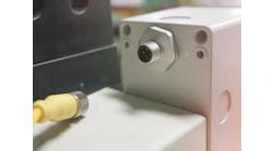
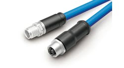
Copper conductor Cat. 5/6/7/8 cables commonly use RJ45 modular connectors, but they aren’t as effective in an open environment. For this reason, M12 connectors are usually used for this purpose. Most manufacturers will offer cables that are RJ45-to-RJ45 as well as combination cable sets to take RJ45 to M12 or vice versa.
To further identify communications cables from other cables in the M12 world, variations of the standard M12 connector are used. Commonly in use are A-Code, B-Code, C-Code, D-Code and X-Code, with L-Code, P-Code, S-Code and T-Code also in use. The purpose is to prevent cables from being plugged into the wrong circuit.
Fiberoptic connectors vary on the use and number of fibers in the cable. The most common and oldest variation is the straight-tip (ST) connector. This is simply a bayonet-style plug-and-socket arrangement.
Subscriber connectors (SCs) step up from the ST style by providing a square connector around the round fiber core. These tend to have latch mechanisms to secure the plug to the socket.
Lucent connectors (LCs) take that technology further with more robust connections and a smaller profile than both the ST and SC style. These are often found in telecommunications applications.
A final type, multi-fiber push-on (MPO) connectors, as the name suggests, are used where there are multiple fibers of various diameters in the same cable assembly.
These are but a subset of the myriad possibilities for data communications cables and connectors. The applications are evolving. For example, a new technology has been released that cuts the Ethernet cable down. Single-pair Ethernet (SPE) not only transmits along a single twisted pair, it also supports simultaneous power supply of the end devices via power over data line (PoDL). Who knew, back in the days of multi-conductor machine cables, that we would get to a day where we could both power and communicate with a device over a single pair of conductors? The future is exciting, and it’s great to be a part of that journey.


