A cause-and-effect matrix (CEM) is a decisive way to lay out alarms, interlocks or conditional interactions. The benefits of putting data into a cause-and-effect matrix is the table format simplifies the understanding of the relationship between the cause and the effect.
Historically, engineers may find cause-and-effect matrixes in Six Sigma and quality-assurance applications for tracking quality errors or figuring out where processes go wrong, but the idea is applicable all around industrial programming and operations. CEMs can be used to document findings from a safety risk analysis and then pinpoint specific mechanical and electrical equipment required to lock out, as well as controls and alarming. CEMs are also easy to use as checklists when testing during I/O checkout.
Traditionally, the CEM was utilized in process control for emergency shutdown checklist situations. Also, fire and gas systems utilize cause-and-effect matrixes. Table components are causes, effects or, in this case, actions.
If you are a programmer, it’s easy if it’s related to an “if, then“ statement. For instance, if, while driving a car, the operator does not put fuel in the car and keeps driving. What happens? The fuel light comes on as a warning. Soon after, the car engine stops responding. The operator then sits pushing on the pedal and cussing because the driver is stuck in traffic and going to get rear-ended. Machine safety has similar causes and effects. For instance, if an operator can run a machine without a guard and the machine has moving parts, the operator may not go home with the same appendages they arrived with. Figure 1 shows a sample conveyor start/stop table.
The CEM is not a substitute for line drawings, but logic can be derived from CEMs. It might look like this:
If Conveyor_Guard_On and Machine_Start_PB and Machine_ControlPower then Machine_Start_Ok.
If Machine_Start_Ok and SpeedRef_MotorA and Not_ConveyorON then Start Conveyor.
This is a simple example, but it also poses an issue or sets up a condition. For instance, the table shows that the guard is on for “stopping the conveyor.” What if the conveyor is running and someone takes the guard off without stopping the conveyor? Is this a problem?
The effect called “conveyor started” means the conveyor is running, so the logic here shows that the guard must be on for the conveyor to run. But the stop condition, should be changed for conveyor stop (Figure 2). Figure 3 shows the CEM with corrected logic.
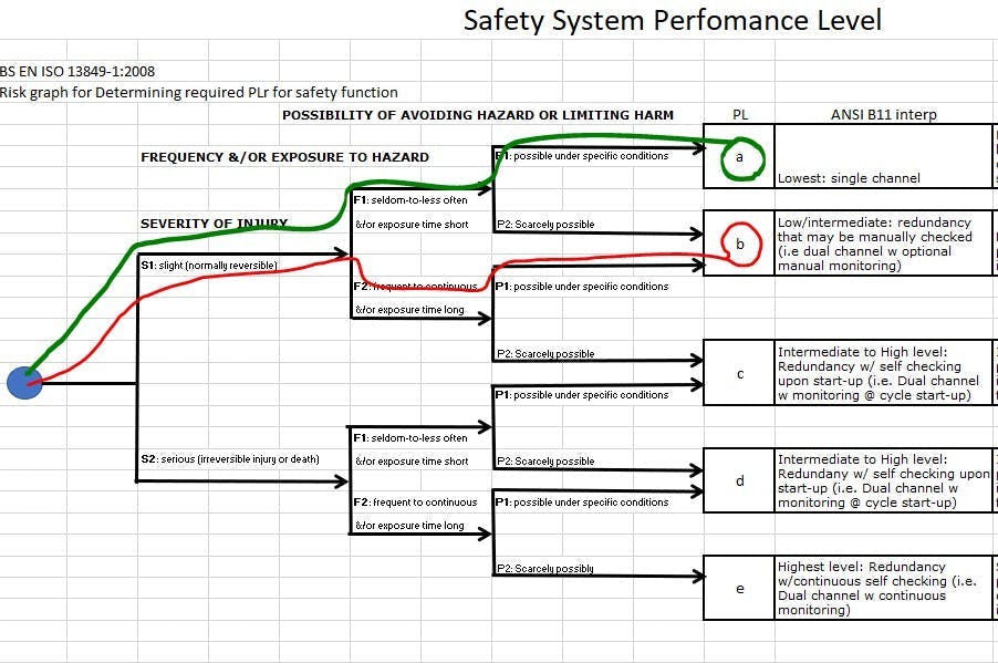
Can this be related back to a safety risk assessment based on International Organization for Standardization (ISO) 13849-1? Yes.
How does a CEM relate to the safety requirements? The I/O specified for the field can be made into a two-channel safety locking device and flagged for a safety input instead of a regular input. Also, the CEM table can be used to show that the safety was integrated into the control scheme or used to inspire the safety risk assessment. The idea is that the cause is documented, and the effect is mitigated.
It’s more important to understand that the controls are interfaced with safety, since the industry has gone toward smart relays and safety programmable logic controllers (PLCs). Separating interlocks and safety inputs and outputs (I/O) from regular I/O may be dauting at times or repetitive, so if a table can be used to organize it then it should be utilized. Furthermore, data from a table easily goes into pseudo code and allows the segmentation to be seen for function blocks.
For this example, if a system had five conveyors, then the motor starter sequence and the commands and outputs for the “conveyor function” could be quantified and then turned into a function block for repetitive calls. This leads to a user-defined data tag (UDT) type scenario, and segmentation of the safety I/O so that the result would be five small tables pointing to five different sets of I/O and writing code for the functionality once.
For machine builders, the safety risk analysis can reference the CEM, and then there is a direct connection to the implementation of mitigation, and the path to the I/O components related to machine guarding is clear. The cause and effect must match the safety analysis requirements. Also, it’s easy to bring out the CEM tables during testing or training, and people have a table representation of what the interlocks and I/O are for the required function. However, the dependency is on whether the table is filled out properly. This makes testing I/O and safety easier and provides a checklist for making sure no points are missed. In conclusion, CEMs are a multifaceted tool that can be used for safety risk analysis, programming and training.
About the Author
Tobey Strauch
Arconic Davenport
Tobey Strauch is currently managing brownfield installations for controls upgrades at Arconic Davenport. She has previously worked as principal controls engineer and before getting her bachelor’s in electrical engineering, was a telecommunications network technician. She has 20 plus years in automation and controls. She has commissioned systems, programmed PLCs and robots, and SCADAs, as well as managed maintenance crews. She has a broad mix of mechatronics with process control. She enjoys solving problems with Matlab and Simscape. Contact her at [email protected].

Leaders relevant to this article:


