At the University of British Columbia (UBC) in Vancouver, Canada, a group of determined students faced a technical task more challenging and with greater real-world implications than presented by typical homework or exams. They needed to safely test-fire an actual rocket engine to verify correct operation prior to launch.
The UBC Rocket student team consists of over 100 students working on multiple rocket projects. About one third of this group are engaged in the UBC Rocket Spaceshot project, working to build a sizable 25-foot-tall rocket powered by a liquid propellant engine. The rocket alone would weigh about 450 pounds empty and 1800 pounds when loaded with propellants. As part of designing and building the rocket, the project required in-house creation of a custom propulsion system, the most complex part of the rocket.
About a dozen students focused entirely on designing and manufacturing evolving generations of the rocket engine, machined and assembled out of steel and aluminum parts. Once each propulsion system was developed, the team needed to test the engine control, functionality and performance on the ground, so they could verify the overall rocket design before flight. This meant developing and qualifying some form of test stand and associated automation to control and monitor test runs.
After some initial research, the team realized that controlling and monitoring a rocket engine on the ground was much like operating an industrial machine. This led them to conclude that a programmable logic controller (PLC) platform would be ideal for the task. This article shows how they created a PLC-controlled rocket engine test stand, improving and adapting it as requirements evolved.
On the job learning
The student team is made up of dedicated and motivated individuals who embrace the challenge even though it is over and above their normal school and work commitments. For many, it is one of the few opportunities for Canadian citizens to engage in this type of aerospace and rocketry program. The UBC Rocket student team provides a professionally organized way for the students to gain valuable aerospace and engineering experience.
Actually launching the rocket is the ultimate goal for the team, but like any large project, this one is organized from smaller projects. The rocket engine test stand is one essential piece of the larger rocketry project, with every element of the program critical to overall success. Much of the math and science behind rocketry is covered in the classroom, but for real-world implementation the students would need to learn a lot on the job.
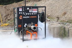
Figure 1: The rocket engine, shown here attached to the test stand, must be controlled to carefully combine and ignite liquid oxygen and kerosene while monitoring results.
(Source: AutomationDirect and UBC Rocket)
A few team members were assigned to find out the requirements for controlling the rocket engine, and to then specify and design control hardware and software to create the necessary test stand system.
It is rocket science
For the team’s rocket, the engine size was specified early in the design. The liquid propellant engine combines liquid oxygen with kerosene and a source of ignition, with the resulting combustion developing about 3400 pounds of nominal thrust. At full power, the engine consumes about 15 pounds per second of the fuel and oxidizer propellants combined, with the combustion chamber operating at about 200 pounds per square inch of pressure.
The test stand would need to remotely, reliably, and safely control the engine for a test run (Figure 1). It also monitors and stores the results of each firing for later analysis.
Test stand automation operates valves and actuators, monitors sensors, initiates ignition, and provides various safety shutdown functions. The last item is critical because a properly designed control system can recognize instrumented problems within milliseconds and act to drive the system to a safe state. No personnel were ever expected to be anywhere near the engine in operation, but the team also needed to protect the equipment from damage.
Because the team was learning so many disciplines at once, there was a great desire to avoid re-inventing the wheel. They already knew that PLCs and other industrial devices like control valves and sensors could do the job if they selected the right parts and programmed them properly. Here’s how the team specified the required hardware and software.
Control of real-world science
After some initial investigation, the team targeted AutomationDirect products for the PLC platform, with the AutomationDirect website’s features assisting in this decision. Online product selection guides quickly helped the team focus on the Productivity2000 micro-modular PLC platform as it had plenty of computing power, I/O options, and configuration flexibility.
Selection of the Productivity2000 was reinforced by the wealth of online product documents, support information, and training videos. Even though none of the team members had ever programmed or even heard of a PLC prior to this project, many members were familiar with other contemporary languages such as C++ and Python.
Using the free software and online tutorials, the team quickly discovered how to configure and scale inputs and outputs, and create the ladder logic necessary to achieve control. This gave them plenty of confidence they could meet their goals. The team was very excited for the hands-on opportunity to work with real-world products and systems, which isn’t always possible at university. However, they needed to be mindful about incorporating the “minimum viable product”, engineering-speak for keeping it simple and economical.
Mission control
The test stand design and development process evolved in several ways. Initially the design team tried using stepper motors to control valves, but they found this approach to be difficult and unable to provide the necessary feedback. They moved to using pneumatically actuated valves and electric solenoid valves, both easily interfaced with the PLC via relays. As development continued, more valves were progressively automated, eventually reaching a total of 12.
For instrumenting the test stand and rocket engine, temperature and pressure sensors sourced from AutomationDirect were specified for the necessary ranges and service. Industry-standard 4 to 20 mA signals ensured straightforward connection to the PLC and provided reliable signals.
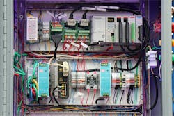
Core automation elements were assembled into a control panel mounted on-board the test stand (Figure 2). The team designed and fabricated the control panel using a variety of hardware and cables obtained from AutomationDirect.
Figure 2: The team designed, fabricated, and wired a control panel mounted on-board the test stand, featuring an AutomationDirect Productivity2000 PLC, with ZIPLink connector cables installed at the top.
(Source: AutomationDirect and UBC Rocket)
Test stand operation encompassed several types of functionality including:
- Valve control
- Ignition
- Auto-abort
- Status and data logging
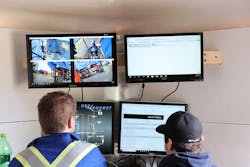
The team developed a human-machine interface for monitoring and control of test operations from a remote operating location, and also used video recording (Figure 3). Complete valve control is generally achieved through timing sequences programmed into the PLC so all actions can be performed repeatably and precisely once triggered by the operator. For a typical test session, an operator remotely actuates valves while a technician performs the propellant filling. Once propellant tanks are filled, the technician joins the operator in the control bunker where they set the test parameters.
Figure 3: The test stand is remotely monitored by team members.
(Source: AutomationDirect and UBC Rocket)
Before a test can begin, the PLC enforces that all valves are in the correct state. The operator initiates a test and the PLC takes over automatic control of valves where timings are scheduled with millisecond precision. To begin, valves sequentially open to mix fuel and oxygen in the igniter, a small chamber which shoots a flame into the main rocket engine. Following this, the PLC outputs a 4-20mA signal to precisely command positions of the main propellant valves with better than 1° of precision as they follow a pre-programmed profile to ensure smooth engine startup. Once the propellants enter the engine’s combustion chamber they mix and are ignited by the igniter, which is then shut off.
As the test reaches completion the main propellant valves close and are followed by a sequence of valves automated to inject inert gas into the engine and surrounding area to clear any residual propellants and suppress any small fires. Closely tied with the normal valve and ignition functionality is the complementary auto-abort logic. The program is configured so any sensed anomaly will abort operation, driving all valves closed and other devices to their safe state. The team has experienced engine startup sequences that were abnormal and the test was reliably shutdown each time by the PLC.
For each test run, all device status and instrument data are data logged to the PLC’s built in webserver. This allows quick, remote access of data for export in CSV format after the run so the team can perform more detailed analytics using other PC-based software. Being able to remotely access the data from within the safety of a control bunker enables the team to efficiently run back to back engine tests.
3-2-1 ignition
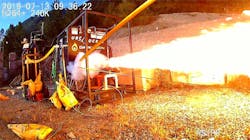
In 1961 as the Mercury Freedom 7 launch experienced delays, an exasperated Alan Shepard is said to have barked “light this candle” to mission control. However, any rocket program has extensive tests leading up to the proverbial candle lighting moment (Figure 4).
Figure 4: The testing regimen progressed from dry cycling, to water tests, to ignition tests, to the final live fire operation.
(Source: AutomationDirect and UBC Rocket)
The UBC team members extensively and progressively tested their rocket engine test stand to ensure proper operation. Hundreds of test runs were performed, first operating dry to just exercise the controls and the equipment. Later the systems were operated with water so certain control and monitoring could be safely achieved without introducing propellants. Because reliable ignition is a must, the team next performed over 60 igniter tests before ever filling the system’s supply tanks with propellants. Finally, the team conducted a series of cryogenic checks where the liquid oxygen plumbing was tested with liquid nitrogen to ensure that all sensors and valves operated nominally when exposed to cryogenic temperatures.
Eventually the team performed actual and complete live fire tests. As of this writing, there have been multiple fully operational test sessions, with five total firings. All systems and automation elements have operated consistently and as expected.
ALSO READ: How to get a boat in the water
A platform for the future
Choosing and implementing commercially available AutomationDirect PLC controls and instrumentation enabled the UBC Rocket team to rapidly develop a reliable automation platform. It also gave them the ability to readily adapt the system to new and changing requirements.
For instance, the team was able to progressively transition manual valves over to automatic valve control. They also upgraded the propellant valves to pneumatic valve positioners, enabling them to throttle flow rates during key startup sequences. Currently the test stand is trailer-borne, but upcoming construction phases are adapting the design to fit in a shipping container, with more automation for fire suppression and propellant filling.
UBC Rocket team members began the project with plenty of passion, but perhaps somewhat less hands-on experience. They were enthused to find how AutomationDirect systems and support helped them build skills and produce a reliable automation solution. The team repeatedly found that AutomationDirect offered the wide portfolio of products they needed, suitable for the difficult field operating conditions, at a good price point.
Sponsored Recommendations

Leaders relevant to this article:

