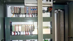
Control panel design starts with the basics, and it's not just about selecting a cabinet and back panel to house your electrical control hardware. It's about creating a design to control a machine or process. To do that, hardware must be purchased and mounted on a back panel and then wired and integrated into the machine. None of this or the testing that follows can be accurately completed without the drawings. Where are the drawings? Control panel design creates the drawings.
The automation cannot be brought to life and properly maintained for years without a proper control panel design. The design could be a sketch or created using graphical software to get the lines on paper, but preferably CAD or electrical CAD is used to create it. It should also follow standards such as found in the NFPA 79: Electrical Standard for Industrial Machinery, among others. Get a copy; read it; then continue here.
Every control system needs a control panel design, and that includes drawings—the electrical schematic. Building and wiring a panel without the design represented in a schematic is like mopping the floor without sweeping first; when complete, it's just a bad job. Drawings are always required, just as installing wire numbers, on all wiring in an industrial automation control panel, is always required.
Control panel design 101
To create a proper control panel design, get the broom and start sweeping. Start creating the drawings including a table of contents, functional diagram, power distribution, I/O diagrams, control cabinet layout, back panel layout and bill of materials in a schematic.
The lazy guys don't include the table of contents in their schematics, but at least the good designers do. Many designers also do not include a functional diagram. However, it's good design practice to have a picture, 3D model or block diagram of the machine with descriptive text pointing to all major components, input and output devices and stations or functions. It does take a little time to create the functional diagram and related sequence of operation that should also be included, but it’s worth it. It helps to get the engineer or technician familiar with the control system design. Get with the mechanical designer because the functional diagram is a great way to tie the two disciplines, mechanical and electrical, together. At a minimum, draw a top view block diagram and point out I/O details and machine functions.
The 480/240 Vac, 120 Vac and 24 Vdc power distribution diagrams should each have their own pages. The same is true for the safety circuit and miscellaneous control circuit diagrams. Keep them on separate pages as they are clearly different control functions and are often separated on the control cabinet back panel and in the field. Spreading things out can help to organize and simplify the schematic and related troubleshooting compared to packing the schematic full of dissimilar devices all in a few pages.
Include detail drawings of the I/O and limit it to two I/O modules per page to keep the control panel design drawings easy to read. The input or output descriptor must match descriptors in the PLC program. Both must match because that is the correct way to do it and eliminate confusion. It takes little time to match a "raise cartridge gripper" description on an output to a solenoid or "cartridge gripper raised" description on an input from a sensor to the program descriptors. It will certainly take more time for you or others in the future if you don't.
Finally, we get to the control cabinet layout detailing the cutouts and cabinet-mounted devices. The environmental rating of the control cabinet final installation location should also be considered. Washdown areas may be obvious and have clear requirements such as NEMA 4X, but general industrial-use control panels need to be protected, as well. It's a good idea to use a minimum of a NEMA 12 enclosure to protect from water ingress from drips or splashes. Don't buy a cheap control enclosure, or your dripping mop may short out a power circuit in the control panel.
The back panel layout is another subject, but lay it to scale in the drawing, or it just may not fit. Also, group similar voltage-level devices or functions together. It keeps the potentially noisy hardware, such as variable frequency drives, servo amps, power contactors and relays, away from the low-level signal hardware such as the controller and analog signals. Pull it all together with a bill of materials (BOM) of your favorite vendors’ hardware. The BOM is for the control panel hardware, so keep field devices separate if you can.
The final control panel design is successful if you can build a duplicate of the control panel a year from now. If not, add more details and update the design as needed. Also, be sure to include changes or as-built redlines in the final drawings. While an almost correct electrical schematic is better than none, it is not how it should be done. That's the basics.
Advanced courses—electrical CAD
Draw all this up, and you have a control panel design. If you do it regularly, consider electrical CAD instead of a hand-drawn sketch, or basic CAD or graphical software. The electrical CAD software can help to standardize electrical symbols and part database, along with automating some of the design processes, such as adding wire numbers and cross referencing devices—all important design tasks.
The cheap or free programs that have every feature may work great, or they may be too good to be true. Spending a little money for tight integration into all design drawings, along with a look ahead to the IoT, Smart Industry and Industry 4.0, will make spending some money on electrical CAD a good decision.
About the Author

Dave Perkon
Technical Editor
Dave Perkon is contributing editor for Control Design. He has engineered and managed automation projects for Fortune 500 companies in the medical, automotive, semiconductor, defense and solar industries.

Leaders relevant to this article:
