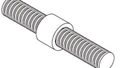
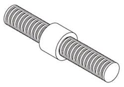
"We've used lead screws in our linear motion applications for years because they give us high stiffness, very acceptable backlash, and simplicity. As performance requirements increase, we're going to have problems with the lead screws not accelerating quickly enough to high speeds. It looks like we have some torsional issues as well. Can we overcome this with better sensing and control? Is it time to look to an electronic answer?"
—From July '12 Control Design
Answers
Performance Limitations
As the market for linear actuators grows, so too will the demand for faster and longer actuators. When it comes to electrical actuators, lead screws have been the main go-to solution because they provide a high mechanical advantage in a compact envelope. Their position, speed and force can also be easily monitored with the application of a feedback device such as an encoder or a load cell. However, there are limitations to increased performance at longer strokes and higher speeds.
One of the potential problems when seeking higher speeds is not being able to accelerate fast enough to achieve a given peak velocity. For example, if an application has an actuator with a really short stroke of 7 in. and it needs to accelerate to a peak velocity of 20 in./s, it will have only 3.5 in. of stroke in which to accelerate, given a typical motion profile. However, the actuator may only be capable of a maximum acceleration of 90 in./s². In actuality, for this actuator to reach the target speed, acceleration would need to be 114.3 in./s².
The limiting factor is mass, as in Newton's second law, where force is equal to mass times acceleration. For rotation applications, the required torque would be equal to the polar moment of inertia times the angular acceleration.
This means that, given the same torque, the more mass the lead screw or motor has, the slower the acceleration will be. The same applies to its inertia. One solution could be to install a larger motor with more torque, but it will have greater rotational inertia because its mass is farther from the axis of rotation. A better solution would be a coreless motor with high acceleration and low inertia.
A problem inherent to long lead screws is that the angle of twist makes it behave like a torsional spring, storing and releasing energy with changes in angular momentum. This could lead to small errors in position. A method to correct for this would be to drive a little past the desired position to compensate for the position error. Another method would be to change the lead screw's geometry by switching to a larger-diameter hollow screw or preloading it in tension.
The only electronic solution is to monitor what is happening and respond accordingly. Proper placement of these monitoring devices is critical, and the closer the monitoring is to the output, the better the response. Most linear actuators monitor the angular position of the lead screw, but this does not account for the error caused by lead screw twist, backlash and changes in length from compression or tension.
It would be better to monitor the position with a linear-style encoder such as an optical transmissive, optical reflective or absolute magnetic style. The magnetic style is unique in that it has tiny grooves etched in it that a read head can sense (Figure 1). Magnetic-style encoders are robust and do not require recalibration.
Andrew Oudhraj,
mechanical engineer,
Tolomatic, www.tolomatic.com
The Cost of Speed
Screws are, by design, mechanical reduction devices. They increase the torque output of the motor while reducing top end speed and acceleration. Speed and acceleration can be increased by changing the pitch; however, this will typically result in increased backlash and reduced accuracy.
Travel length will also limit the top end speed because the resonant frequency of the screw decreases as the length increases. Going with direct-drive linear motor technology eliminates all these problems, and will result in improved accuracy and a longer operational lifetime.
The higher speed and acceleration come at a cost. Linear feedback devices and linear motors tend to be more expensive than a rotary motor with a lead screw, and the technology requires a counterbalance system when used in a non-horizontal orientation.
Ron Rekowski,
director of product management,
Aerotech, www.aerotech.com
Consider the Lead
As with most technical questions, I typically like to ask about 10 more clarifying questions before I make a recommendation.
For starters, it would help to understand what acceleration you are trying to obtain. Under ideal conditions, a lead screw can accelerate at 20 m/s2. If you require accelerations that are significantly larger, you will likely need to look at alternate drive train technologies, such as a linear motor, which is capable of 50 m/s2 or greater. If an acceleration of 20 m/s2 would satisfy your application's requirements, please read on to see what might be limiting your current system's performance.
There are several factors that will limit the acceleration that any screw is capable of. The most common limitation is the critical speed of the screw, also known as "whip." Critical speed is defined as the eccentric motion of the drive screw that occurs when the rotational velocity (rps) of a screw is exceeded. If the screw's critical speed is too low, then the ability to accelerate will also be limited.
Fundamentally, a screw's critical speed is a function of two variables: the diameter and the length of the screw.
where N is the critical speed, d is the screw diameter, and L is the length between bearing supports. Note that the formula assumes both ends of the screw are rigidly fixed.
The critical speed and the screw diameter have a direct relationship, so an increase in diameter will increase the critical speed. However, the critical speed and the screw length have an inverse relationship, so the longer the screw is, the lower the critical speed will be (Figure 2). Knowing this, the acceleration capability can be improved by either increasing the screw diameter, shortening the screw length, or some combination of both.
Another way to avoid critical speed issues, while increasing acceleration capability, is to change the lead of the screw you are using. The screw lead is the axial advance that is realized from one complete turn (360°) of the screw. For example, a 5 mm lead screw will have a linear translation of 5 mm per screw rotation. Increasing the lead of the screw will increase the speed and acceleration attainable without increasing the critical speed. Please note that by increasing the lead of the screw, you will sacrifice some mechanical advantage, and the torque required from the motor will increase as well.
If critical speed is not the issue, then there could be an issue with the amount of torque available. If you consider the components that make up the total required thrust force (acceleration force, force of gravity, and force of friction), the force required to accelerate your load is the largest contributor. It is possible that the motor you are using does not have enough torque to reach the accelerations that you are trying to achieve. There are relatively simple calculations that can be done to see what your maximum required torque is. Once that is known, you can make sure that your motor is properly sized to reach your desired accelerations.
Your question also refers to a solution with "better sensing and control." You don't mention what your current setup is, but if you are using a stepper motor that is an open-loop system, switching to a closed-loop servo motor solution, which certainly could be considered to have better sensing and control capabilities, could help in a roundabout way. As I mentioned, acceleration is all about torque. When you look at the continuous torque of a similarly sized stepper motor and servo motor (NEMA 23, 3 stack, for example), you will find that their torque densities are relatively close. The servo motor, however, has a peak torque region that a typical stepper motor will not have. This peak torque region allows the motor to put out some multiple of the continuous torque (our motors are rated at 3x) for a specified amount of time (our motors are rated for roughly 10–30 s based on winding and frame size). The ability to increase the torque output for a short period of time allows a smaller servo motor to solve applications where the acceleration torque requirements exceed that of the continuous torque rating on the stepper. With all of that said, though, increasing the size of the stepper motor — to, say, a NEMA 34 — could give you a continuous torque rating that is large enough to satisfy the application's acceleration torque requirements.
If none of the above suggestions yields the acceleration performance you require, I would recommend that you start looking at alternate drive trains to meet your acceleration requirement. If high stiffness, low backlash and high accelerations are the goal, then we will likely be looking at a linear motor to meet your application's requirements. The linear motor does not have the mechanical limitations that screw solutions do. Additionally, if the linear motor solution you go with is a servo, you will gain the sensing and control functionality associated with a closed-loop system. The downside of this path is that a servo-driven linear motor system is typically more expensive than a rotary motor screw-driven solution.
Mike Szesterniak,
marketing manager — life sciences,
Parker Hannifin, www.parker.com
Minimize Compliance
Often times in mechanical systems, the true culprit in poor system performance is at once obvious and overlooked. Minimizing the compliance between the rotary mover and the linear end effector can be the most effective way of improving the performance of a linear system. The use of belts, pulleys and couplings can result in unwanted compliance that can result in poor overall performance. Often, this is a bigger contributor to poor positioning performance than a poor inertia ratio.
Reducing mechanical system compliance is an effective strategy to improving performance because it is addressing the root cause of the issue. The most effective way to eliminate compliance in a lead screw application is to use an integrated linear motor. Having the lead screw incorporated into the motor for an integrated solution eliminates the belts, pulleys and couplings that cause the compliance and leads to performance issues.
Clark Hummel,
application engineering manager,
IMS Schneider Electric Motion USA,
www.se.com
Linear Motor Advantages
Many applications in motion control require linear translation of rotary motion. Belts, ball screws, and rack and pinions can resolve some of these issues, but eventually, as performance requirements increase in both accuracy and repeatability, a different linear technology should be considered. Often the considerations can be of higher-quality components — stiffer belts, lower-backlash gears, and different ball screw mounting can help, but these are not free. You must account not only for the higher cost of better components, but also increased friction from pre-load increases. The critical speed of lead screws can result in limitations of top speed, acceleration and moving mass sometimes well below requirements.
Alternatives exist, however. Linear motors have existed for many years. Advantages of linear motors come from the direct attachment of the load to the motor without any translational devices. When the backlash, compliance and other errors from the translational components are eliminated, increases in the performance can be achieved.
Feedback is another advantage of using a linear motor. When looking at most rotary applications, using the encoder on the motor for positioning results in the feedback being located at least two mechanical components away from the end effector. With a direct-drive linear (DDL) solution, the feedback for the motor is the same as one for the load quite close to the end effector. The result is a higher-bandwidth control (less error during motion), higher repeatability and higher accuracy.
Linear motors have found their way in the machining, electronic assembly and packaging industries. For example, a water-jet cutting machine can be operated with higher accelerations and throughput using linear motors. When you eliminate a translational device, you eliminate its inherent degradations of backlash, friction, accuracy and compliance. When this is done, you have the ability to operate with higher bandwidth, accelerations, speed and accuracy.
Lee Stephens,
senior motion control engineer,
Kollmorgen, www.kollmorgen.com
More on the Linear Front
Conventional solutions like lead screws for turning rotary movements from the motor into linear machine movements have some advantages. Such machine solutions are easy to develop and fairly easy to integrate into a machine. Complete drive-motor-lead screw solutions have existed on the market for a long time. Various drive functions can compensate for disadvantages like backlash.
But when it comes to highest position and traversing accuracies, extreme acceleration demands or lifetime/maintenance, the trend is clearly going to direct drive technology with linear motors. Linear motors are directly integrated into the machine without additional mechanical devices to convert a rotary movement to a linear movement.
Together with a linear feedback device, there are no longer the disadvantages of backlash or maximum torsion/speed. The only limiting accuracy factor is the accuracy of the linear encoder (in the micron range); and acceleration is limited by the available maximum force of the motor. Several motors can be used in parallel to multiply the available force to get highest accelerations.
It might be challenging to develop a completely new design using rail/sliding guides, linear motors and linear encoders to increase the machine accuracy and productivity, but some companies offer complete solutions for rail guides/linear motor/linear encoder to shorten the machine design phase.
Harald Poesch,
product manager, motion control motors,
Siemens Industry, www.siemens.com
Straightforward
The answer is simple: Replace the lead screw with a linear motor. Linear motors are capable of accelerations up to 20 g and speeds up to 5m/s. System performance is increased by providing a direct-driven payload and position feedback directly at the payload. The direct connection to the payload increases system stiffness and eliminates any potential compliance, backlash and friction associated with the rotary-to-linear transmission components. The direct position feedback also allows for increased positioning accuracy.
Paul Zajac,
product engineer,
Yaskawa, www.yaskawa.com
High Speeds or Heavy Loads
Without knowing the magnitude of the specifications, it is difficult to say whether a lead screw is capable of performing well in a particular application. However, lead screws are suitable for high accelerations because they do not suffer from ball skidding problems associated with ball screws.
The limiting factor with a lead screw nut is frictional wear and heating created by the sliding surfaces of the thread. This is known as the pressure and velocity (PV) limit. Various nut materials have different limiting PV values. These limits should not be exceeded during operation. A lead screw can thus move at high speed under light loads or move at slow speeds under heavy loads, but it will have difficulty doing both at the same time.
Torsional stiffness is a factor of the screw and nut geometry and material properties. To improve performance, the screw diameter-to-length ratio should be as large as practical. Theoretically, a large-diameter hollow screw manufactured from stiff but light material would perform best. The benefit of this construction in most applications would not justify the cost. Solid stainless steel screw construction offers a good performance-to-cost ratio.
Robert Lipsett,
engineering manager, Thomson BSA
Thomson Industries, www.thomsonlinear.com
Monitor Conditions
When you've reached the limits of lead-screw performance, linear motors can be considered a possible solution. They have excellent acceleration, high force density, very smooth operation and extremely accurate positioning.
Linear servo motors can achieve acceleration of 30 g, speeds up to 10 m/s, and extremely accurate precision. There are also linear motors available that feature an ironless core, eliminating cogging. As a result, this permits high control loop gains, yielding even better positioning accuracy. A highly dynamic control system is useless without highly capable control software. From the Beckhoff standpoint, motion systems are best programmed via a centralized, PC-based software platform.
Also, machine builders are utilizing the considerable bandwidth of industrial Ethernet systems for machine-improvement solutions in addition to traditional I/O and motion control. For example, it's possible to implement condition monitoring I/O that can measure machine performance, mechanical wear and tear, energy consumption, heat, vibration and more. Even if you're unable to eliminate all the leadscrews in the application, I/O terminals with integrated functionality can help determine if mechanical components are in need of repair or replacement. Simultaneously, downtime can be reduced by understanding when conditions, such as degradation of mechanical assemblies, hint of a possible developing failure.
This combination of linear servo motors, PC-based control platforms, industrial Ethernet communication and I/O terminals for measurement functionality could be an ideal fit for your application, depending on your specific requirements and goals.
Matt Lecheler,
motion specialist,
Beckhoff Automation, www.beckhoff.com
Sponsored Recommendations

Leaders relevant to this article:


