By Markus Tarin, MoviMed
The complexity of machine vision inspection applications varies greatly depending on the speed of the operation and the detection tolerances required to ensure quality.
Implementing a machine vision application to gauge 20 cylindrical parts per second that are 2 or 3 in. long and 9 mm in diameter to micron tolerances at line speeds of 52 in. per second falls in the complex category, even for an experienced machine vision integrator such as MoviMed, based in Irvine, Calif.
Founded in 1999, MoviMed was established to meet the needs of the medical device community in Southern California. Our business quickly expanded beyond that market as two key changes occurred: Machine vision and motion technology became more refined, and custom applications for vision, motion, data acquisition and inspection became the norm for most manufacturing and research firms, irrespective of their market.
The Task at Hand
The metal cylinders in question are made out of a brass alloy. The parts are made from small metal "cups" that are drawn into a hollow cylinder. The resulting part has small features, such as a little lip, a slant angle and an undercut. "All of these features are critical for proper functioning of the system since a precise mechanical fit is of the utmost importance," says David Ritter, scientific technologist—real time systems at MoviMed. "The custom machine vision system required must gauge multiple mechanical dimensions of the part simultaneously. Some critical dimensions are overall length, part width at various critical locations, slant angle and resulting width at predetermined part lengths, and thickness of the lip and size of the undercut."
The producing machine was equipped with an '80s-era optical-gauging system. Besides obsolescence issues, the system was not measuring up to desired tolerances. Our company performed some calculations and optical simulations to approximate the old system's performance as a baseline from which to work. "It turned out that the old system was limited primarily by the optical path—mainly a custom lens design that could not reproduce details better than about 100 µm at a contrast level of at least 50%," Ritter explains. "Second, the image sensor used was a line scan sensor with only 128x1 pixels. The system used an averaging technique to try to overcome some of its limitations."
Another flaw in the original design was that critical measurements were based on indirect references derived from the tooling and part fixture and not measurements of the part itself. This invariably led to measurement drift caused by mechanical wear and tear.
What Technology to Use?
While we evaluated technology options, our customer evaluated smart cameras for this task with other machine vision integrators with expertise in the smart-camera field. It quickly became apparent that for the complex gauging task and the resolution required—combined with the part repetition and part speeds—smart cameras alone were not suitable as an overall machine vision concept. This project would push the current camera technology, available lenses and illumination, as well as required processing power, to the limits.
The company selected MoviMed for this project given its experience with highly complex, high-performance custom vision solutions. Preliminary estimates and tests with respect to processing power requirements showed that the system would have to run on a real-time operating system for deterministic, real-time image processing needs.
Difficult Optical Challenges
Several factors made this project especially challenging. "At 9 mm diameter and 2-3 in. length, the aspect ratio of the part was problematic," Ritter says. "The specs called for a measurement resolution of 1.5 µm, but even with specialized hardware, achieving the 1.5 µm target would be a formidable challenge. A 16 Mpixel camera with a telecentric lens at 1:1 magnification was specified. However, even with this configuration, our engineers concluded that sub-pixel interpolation would be necessary to increase the effective resolving power of the measurement system."
Sub-pixel interpolation is a purely mathematical method to artificially increase spatial resolution. It is sometimes not practical to design a machine vision system to the exact optical resolution needed. This could be guided by budgetary concerns or the available sensor resolution in relation to available lens choices. More often than not, a compromise between all these criteria needs to be made, especially when dealing with optical systems. You usually can expect a 5-10X increase in resolution using sub-pixel-based algorithms, as long as there are a sufficient number of pixels available for any given feature to interpolate over.
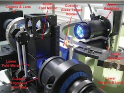
To further complicate matters, there were no standard 16 Mpixel camera lenses available that could meet all the optical specifications. It would be impossible to achieve the minimum spatial resolution of 7 µm using a single camera. So our next best solution was to use two cameras (Figure 1) and a prism that would let us fold one of the cameras out of the way for the 1X optics we needed. As a result, we had to calibrate two camera imaging spaces and combine them as one.
Figure 1: There were no standard 16 Mpixel camera lenses available that could meet all the optical specifications. The next best solution was to use two cameras and a prism. As a result, MoviMed had to calibrate two camera imaging spaces and combine them as one, calibrate for multiple axes of freedom between both cameras and account for a small amount of jitter caused by vibration between the two cameras.
MoviMed
We also had to calibrate for multiple axes of freedom between both cameras and account for a small amount of jitter caused by vibration between the two cameras. To do this, we fabricated a custom fixture to hold a precision calibration target. The target was made of glass with a chrome dot matrix printed onto it that spanned the entire field of view of both cameras. "This allowed us to perform a calibration through both image spaces, thus calculating the mechanical offset between both cameras inherent to the chosen setup," says Carlos Agell, electronic engineer at MoviMed. "The spot size and distance between spots were known and aided in the calibration task. For the basic camera-to-part fixture alignment, we designed a method employing a red laser, a pinhole target and some custom alignment software to calculate the center of image and roundness factors of the laser beam. Each camera was mounted onto an alignment stage with X, Y, Z, pitch and yaw adjustment. At this level of precision, even the image sensor misalignment with respect to the camera enclosure is noticeable and needs to be corrected for."
We chose a smart camera for the top view inspection task because of the much smaller field of view that resulted in a camera resolution requirement of no more than 1.3 Mpixels. We had to inspect for flaws on a recessed shoulder, check for roundness, concentricity, and hole presence and area size of the hole. The initial concept called for only one camera with a top light and a backlight. It turned out that the required combined image processing algorithms running at 20 parts/s was beyond the camera's ability. Hence, we split the task over two identical smart cameras instead.
More Speed Issues
Because of the line speed, the camera would need a global shutter to ensure that motion blur was not introduced during gauging. A single pixel of motion blur could introduce enough measurement uncertainty to exceed the specified tolerances. Therefore, an exposure time on the order of 5 µs was necessary to "freeze" the part and prevent motion blur from introducing gauging errors.
Technical literature still refers to a shutter, although these days it's an electronic timing circuit that affects the exposure time of a sensor. The machine vision world differentiates between sensors with global shutters and so-called rolling shutters. CCD-type sensors have a global shutter. The timing circuit exposes all pixels simultaneously (globally). A CMOS sensor can have either a global or a rolling shutter, but most of them have a rolling shutter, with which a portion of the sensor is being exposed at different points in time. "This raises a significant issue when snapping images of moving parts if that part moves during the exposure period of the rolling shutter's total exposure time," Agell explains. "In this application it would result in a diagonally skewed part, unfit for precise geometrical measurement. It is possible to correct for the skewing, but it isn't practical, unless no other sensor is available. Most rolling-shutter CMOS sensors we looked at had an overall exposure time far beyond the requirements for this application."
System Software and Hardware Components
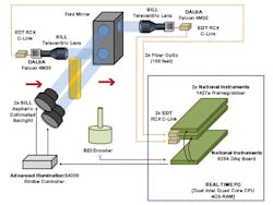
As a National Instruments Alliance Partner, we are very familiar with the company's machine vision capabilities. The selected NI products for the system included LabView Real-Time and NI vision software, two PCIe-1427 Camera Link image acquisition boards, a PCI-6254 Multifunction M Series data acquisition (DAQ) board for encoder tracking, and a PCI-8433 serial interface board for RS-422 communication with the factory PLC. We used two Camera Link cameras for the profile measurements and two Smart Cameras for the cross-sectional gauging (Figure 2).
Figure 2: The components for the system included LabView Real-Time and vision software, two PCIe-1427 Camera Link image acquisition boards, a PCI-6254 Multifunction M Series data acquisition board for encoder tracking, and a PCI-8433 serial interface board for RS-422 communication with the factory PLC.
MoviMed
"This project would have been difficult to complete without the use of LabView Real-Time, NI vision software, and NI hardware," Ritter says. "With built-in multicore support, versatile vision libraries, and PCI Express Camera Link frame grabbers available off the shelf, we were able to divert our attention away from the basic hardware and interfacing issues and toward the difficult domain challenges at hand. The NI tools enabled us to focus on the more esoteric and problematic challenges presented by the requirements and deliver an application that would have been extremely difficult or perhaps impossible using standard tools."
Optical components from Sill Optics included a custom-designed, dual-lens collimated light source and matched Sill telecentric lenses. Advanced Illumination supplied strobe controllers and Smart Camera backlighting units. In addition, we used a rotary encoder for camera triggering and two pairs of Camera-Link-to-fiberoptic converters (Figure 3) to extend the Camera Link cable length to 60 ft, which was required for factory installation.
Figure 3: A rotary encoder triggered the camera and two pairs of Camera-Link-to-fiberoptic converters extended the Camera Link cable length to 60 ft, which was required for factory installation.
MoviMed
To meet the optical system challenges, we combined two Dalsa Falcon cameras to create a single image space. Each camera was equipped with a 1X magnification lens to image the part onto the cameras' 7.4 µm pixel sensors. The minimum shutter speed for these cameras was 15 µs, so we used an Advanced Illumination strobe controller to reduce the overall exposure window. The strobe controller drives a custom Sill (blue LED) backlight with a current of 8 A for 5 µs to freeze the motion of the part onto the two cameras' sensors (Figures 1 and 2).
Going the Extra Distance to Meet the Spec
Although we achieved the goal of 7 µm optical resolution using commercial off-the-shelf (COTS) cameras, it still was not adequate to meet the 1.5 µm measurement specifications required by the customer. Therefore, we indicated edge-detection algorithms with sub-pixel interpolation. "Fortunately, this requirement was well within the capabilities of the LabView Real-Time Module image processing tools," Ritter says.
The NI Vision Development Module offers a large variety of common vision algorithms, some supporting sub-pixel interpolation. However, it sounds much simpler than it is. These "building blocks" are just that—building blocks. In 11 years, we've never had an application that could get by just using canned image algorithms. Every application has to be approached differently, and although the building blocks are a great starting point, a lot of custom programming and special algorithm development becomes necessary to solve machine vision applications successfully.
Performance Challenges
With the optical challenges addressed, the next issue was system throughput. After gauging 20 parts per second, there are only 50 ms left to capture the images, take the measurements, and transmit the results to the PLC to execute the ejection of failed parts in real time, as well as collect and display statistical process data.
"While 50 ms might seem like a relatively large time window in the context of modern system throughput, it is important to note that each of the Dalsa cameras generates a 4 Mpixel image," Agell reminds us. "That means to consistently and accurately apply sub-pixel processing algorithms to 8 Mpixels of 16-bit image data, we need system throughput of 320 MB per second. PCI Express was the only bus option to continuously stream this much image data, so we interfaced the Dalsa cameras to two PCIe-1427 Camera Link DAQ boards. We integrated both frame grabbers into an industrial PC workstation running LabView Real-Time for Phar Lap."
The PC was not a standard COTS industrial workstation. To handle the sub-pixel processing and throughput load for 320 MB of image data each second, our engineers assembled a custom, eight-core Xeon powerhouse with 4 GB of RAM and redundant solid-state drives. The real-time PC supplied the hardware platform and the muscle while a fine-tuned LabView Real-Time application, enabled by the NI vision tools, contributed to the processing finesse to meet the unusually challenging application requirements. The idea was to use multi-core and multi-threading capability of LabView RT to share the processing load of the imaging algorithms between the eight processor cores.
"To meet the rigorous throughput demands, several iterative cycles were undertaken before settling on the final software architecture," Ritter says. "It is not always easy to predict how LabView Real-Time will allocate tasks to multiple processor cores. Therefore, we investigated several gauging strategies and software design approaches to better understand multicore utilization in a LabView Real-Time context. These investigations helped our software engineers find the optimal balance between measurement integrity and system performance."
Operator Needs/Operating Conditions
The operation of this complex system had to be clear enough that factory technicians could run calibration procedures and use the system without difficulty. We designed numerous, easy-to-use graphical user interfaces to support this. We also automated most of the calibration tasks.
The overall system is integrated into a dust-proof, custom enclosure complete with air-conditioning unit. A replaceable window assembly stands in front of the lenses. These windows are coated with an anti-reflective coating to match the monochromatic backlights, hence reducing loss of light caused by transmission losses and reflections.
Although this system has been specifically designed for this application, many of its elements can be translated easily to similar applications.
Another challenge was operating environment. The factory is not air-conditioned, resulting in temperature swings from about 50 to 120 °F. "The vision system is so sensitive that it can measure thermal metal expansion due to the changes in ambient temperature," Agell says. "The system has to be recalibrated based on ambient temperature to account for these changes. We calculated about a 2 µm expansion for every 10 °F increase in part temperature. This calibration could be automated; however, the customer has not decided to implement this yet."
The project was a huge success. MoviMed was able to meet and exceed the very stringent requirements. One gauging requirement called for a standard deviation of 12.5 µm and our system achieved a STDEV of better than 1µm. For the factory acceptance, the system was scrutinized by two "Six-Sigma Black Belt" statistical experts.
Since the deployment of this system, technology has made further advances. Given the opportunity to build a second-generation system, we would probably look into solving this application with a single-camera approach and a custom lens design. This would simplify the calibration and alignment effort and overall system complexity.
Markus Tarin is president and CEO at MoviMed (www.movimed.com) in Irvine, Calif. Contact Tarin at [email protected].
Continue Reading

Leaders relevant to this article:
