Better wafer breaking
Loomis wafer building process consists of dicing wafers made of gallium arsenide, indium phosphide, and other semiconductor compounds less than 300 µm thick. Wafers are covered with thousands of copies of a device that a manufacturer wants to assemble. These copies of the chip are separated from each other via Loomis scribe-and-break system. The devices are laid out on the wafer in a grid. The space between the devices is referred to as a street. Streets are typically 50 µm wide and act as the pathway for the scribing process.ETHERNET AIDS MOTION CONTROL
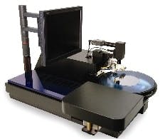
In its most recent quality improvement effort, Loomis decided to use Galil Motion Controls motion and I/O components as the core of its new LSD-150 scribe-and-break system (See Figure 1 below). Galils motion controller, a two-layer module containing the motion controller and the amplifier, and its I/O board provided two communication options: serial or Ethernet. Ethernet was the cleaner solution, explains Cook. Many PCs sold today arent designed with serial ports. They often come with only USB, but most PCs have Ethernet built-in.
Loomis Industries reports its LSD-150 scribe dicing machine is bringing about a new standard in yield, throughput, and cost-effectiveness by achieving +99.5% yields and industry-leading throughput times in 24/7 production environments.
Loomis says it took much time and effort to make certain an Ethernet-based network and infrastructure was correct for its scribe-and-break process. The system includes a PC and the LSD-150 unit, which is used inside environmentally controlled clean rooms.This PC is positioned near the LSD-150 because interaction sometimes is required from the operator via the mouse and the keyboard. A typical, 2-m, unshielded (UTP) CAT5 Ethernet cable connects the PC to the LSD-150. The PC functions as the supervisory controller. All the motors, digital I/O, and analog I/O are controlled and monitored by the Galil components to do the real-time servoing. These components interface with the PC through the BAS switch (See Figure 2 below). Meanwhile, an I/O controller eliminates the need for an external PLC. It includes a 32-bit microcomputer with memory and multitasking for programming various I/O events.
All of the LSD-150 machines motors, digital I/O and analog I/O for its scribing and dicing process are controlled and monitored by Galils components to do real-time servoing, and are interfaced with the units supervisory controller PC through its Ethernet switch.
Dicing in the Streets
THE LOOMIS LSD-150 process begins by mounting the wafer on dicing film that is secured with holding rings. The ring-film-wafer assembly is placed onto the LSD-150 theta stage. Once the ring assembly is clamped down, a support mandrel swings (pneumatically) into position underneath the wafer and film. Next the x-axis moves the wafer to the center position.
Next, the y-axis moves the microscope over the wafers center point, focusing on its surface. The pattern recognition (PR) system begins looking for the patterns programmed for that specific wafers orientation. All the process information is stored in the wafers recipe file; including the patterns used by the PR system, scribe speed, scribe and break forces, etc.
With the aid of the PR system, the LSD-150 system rotates the theta axis, says Cook. It continues with minute rotation adjustments and PR checks until the motion of the y-axis, (scribe-axis, microscope holder, and break wheel holder) is parallel to the streets to be scribed in this direction on the wafer. He adds the x-axis moves the wafer to one side and then indexes back until the first street at the wafers edge is recognized by the PR system. The PR system verifies that the street is centered under the targeting reticule and the processing begins. Next, the y-axis will move out over the far edge of the wafer, drop the scribe tool into the scribe position, and then the y-axis will retract at a predetermined speed. The diamond scribe tool will be pulled across the material, down the middle of the street, creating a crack underneath the visible line made by the scribe tool, he explains. When the wafer is broken, it will break along this line.
Finally, at the end of the scribe stroke, the scribe tool will lift into its non-contact position. Now, the x-axis indexes to the next street. The PR system checks position again, and then the motion repeats. After several streets, if the PR system fails to detect any indexing errors, it will automatically program an on-the-fly pattern, so that positioning can be monitored without stopping the camera over the wafer. Once the first pass is completed, the wafer will be automatically rotated 90 degrees by the theta axis. The x-axis will re-center the wafer, the theta axis will align, and the next pass will start, as before, until processing is complete.


