Control Safety Can Be Intrinsic
Intrinsically safe (IS) equipment is defined by ISA-RP 12.6 as equipment and wiring that is incapable of releasing sufficient electrical or thermal energy under normal or abnormal conditions to cause ignition of a specific hazardous atmospheric mixture in its most easily ignited concentration.
First developed in Britain around 1915 for communications systems in coal mines, IS came into its own for other applications in the 1960s with the introduction of the shunt-diode safety barrier based on the voltage-limiting Zener diode. This provides the ability to use ordinary instrument wiring in hazardous areas instead of armored cable, and the technique provides inherent safety for operating and maintenance personnel because of the low voltages employed.
In general, say the engineers at R. Stahl (http://www.rstahl.com), a circuit only can be made intrinsically safe if it requires less than 1 W of power. For this reason, intrinsic safety is limited to measurement and control circuits. Any circuit powered by higher energy levels requires the use of other explosion protection techniques.
"The expertise in America is very heavily slanted toward explosion-proof and purging," reports Dave Reynolds, vice president, marketing for MTL Inc.(http://www.mtl-inst.com). "IS is considered a European technique. It was developed in Europe, original standards were written for European installation practices, and the major manufacturers of IS products are European, while the major manufacturers of explosion-proof and purge devices are American. Marketing efforts by American vendors are a major factor."
An intrinsically safe system assumes the fuel and oxygen is present in the atmosphere, say the engineers at Omega Engineering (http://www.omega.com), but the system is designed so the electrical energy or thermal energy of a particular instrument loop can never be great enough to cause ignition.
Most hazardous area applications require a signal to be sent from a safe area into the hazardous area, and vice versa. The barriers designed to protect the system must be mounted outside the hazardous area in an area designated as non-hazardous or safe in which the hazard is not and will not be present.
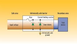
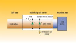
An intrinsically safe system consists of an associated apparatus, either a simple device or an intrinsically safe device, and interconnecting wiring. An associated device is placed in the nonhazardous location between the automation system input/output modules and the connected device in the hazardous location. This device limits the power that can be introduced into the hazardous location to intrinsically safe levels. The traditional means of supplying these connections is through the use of an intrinsic safety barrier. This barrier is a simple, passive device consisting of a zener diode, resistor, and fuse network.
Another type of associated apparatus is the galvanic isolator. Along with providing intrinsically safe connections, these devices also isolate,via a transformer or optically,the hazardous and nonhazardous area circuits. Due to their active nature, most require an external source of power and are application-specific.
Pepperl+Fuchs (http://www.pepperl-fuchs.com) engineers point out the advantages of modular and flexible IS components that include grounding methods such as installation isolated from DIN rail, grounded via isolated DIN rail, or grounded via DIN rail. The addition of an interchangeable safety fuse prevents damage from potential mistakes during start-up operations.
Intrinsic safety equipment must be tested and approved by an independent agency to assure its safety. Products to be installed in the hazardous area can be approved under loop or entity-approval criteria. The loop approval specifies the exact part number and products that can be used. No deviation is allowed. The entity concept specifies parameters that any approved intrinsic safety barrier must meet. This allows the user to select barriers from different approved manufacturers.
As with any solution, there are disadvantages to intrinsic safety methods, as well. Magnetrol (http://www.magnetrol.com) engineers point out this protection method increases installation costs because of the barrier required. In addition, circuit current, voltage, and power are limited, and the total capacitance and inductance of apparatus and wiring must be under certain limits.


