Linear motion products play an important role in industrial automation, and the range of products can now serve a wider market, looking for a faster design on the front end and faster production on the back end. Plug-and-play designs, innovative motion technology and energy efficiency are some of the features making linear motion products smaller, faster and more precise. Six manufacturers—Hiwin, Aerotech, Nexen Group, Nippon Pulse, Ewellix and Bosch Rexroth—share their solutions for linear stages, linear servo motors, rail brakes, electromechanical actuators and single-source system kits.
Stage performance
Art Holzknecht, engineering manager at Hiwin, says developers of motion control and automation systems are being pushed to deliver higher throughput, reduced downtime—higher reliability and reduced maintenance—and better quality—increased precision—all at the same time. Hiwin’s answer to that challenge is its direct drive linear motor stages.
Later in 2021, Hiwin will introduce SDXK, a ball screw driven stage; and the LMXK, a direct drive linear motor stage, was introduced in 2020. These two products round out the XK family of products to serve a wider range of applications, Holzknecht says.
“Hiwin’s XK product family was developed to address a gap in the linear positioning stage market for an affordable, mid-performance stage family,” Holzknecht says. “The LMXK is a direct drive linear motor stage that brings this advanced technology to a greater variety of applications, where it was previously considered too expensive, too complex and high end for general automation and pick-and-place applications.”
While high throughput depends on the application, key contributing factors include reducing move times with high-speed acceleration. “Fast settling into position, reduced jitter—servo hunting—and high repeatability reduces total motion cycle time, so the total process time is reduced, enabling more production in a specified total process time interval,” Holzknecht says.
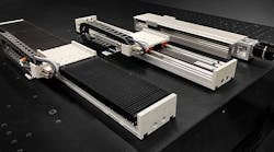
Both the LMXK and SDXK were designed for mid-performance linear positioning applications. With a resolution of 1 micron and repeatability of less than 5 microns, the stages satisfy a wide range of applications (Figure 1), such as pick-and-place, lab automation/drug discovery, robot transport and packaging. The SDXK ball screw stage is ideal for heavier payloads or vertical applications, Holzknecht says.
“Direct drives behave differently than ball screw driven stages. They have very high dynamic response that can cause issues with other machine elements that are not designed for this. Because of their high bandwidth, the linear motor can excite resonances in the system when pushing for higher accelerations. This made them difficult to apply and realize their benefits without servo expertise. Today, advanced autotuning algorithms, notch filtering and other software features have made commission much easier,” Holzknecht says.
Another challenge for direct drive linear products is price point, he says. Historically, they have been a more expensive choice. “The optimized design of the LMXK brings the cost down to where it is competitive with ball screws and belt drives in many applications,” Holzknecht says. “The highly optimized design is elegant in its simplicity.”
Ball screw applications do have a mechanical advantage over linear motors, Holzknecht says. “The ball screw converts rotary motion into linear motion, and the ball screw’s lead—mm/rev—provides a type of gear reduction that enables moving a heavy payload with a smaller motor. It also means the stage is relatively insensitive to load changes,” he says. “On the other hand, a direct drive linear motor is directly connected to the load. There is no mechanical advantage.”
The lead of the ball screw is especially advantageous in vertical applications. “By design, ball screws are very efficient when the motor is driving the load. It is intentionally inefficient when the load is driving the motor, referred to as ‘backdriving.’ A ball screw can support a stationary vertical payload with minimal torque required from the motor,” Holzknecht says.
The LMXK linear motor enables high throughput with acceleration of up to 4 G and speeds greater than 3 m/s. A long stroke of greater than 3 m is available. “You do not necessarily need all of the above in one application, but it does occur,” Holzknecht says. “High-speed pick-and-place systems in electronics assembly machines typically require those specs.” Other applications in high-volume consumer product packaging require fast motion profile execution.
The linear motor is a non-contact drive, free from wear and maintenance-free. It can be mounted with standard T-slots or side cleats. The LMXK also includes a cable chain for cable management. “Extra room is provided in the cable chain for customer cables, so they do not have to figure this out themselves,” Holzknecht says.
Vertical integration with Hiwin’s linear motors, linear guide bearings and integral magnetic linear encoders, combined with in-house manufacturing and system integration, ensure compatibility and easy integration, Holzknecht says.
“When developing the LMXK/ SDXK, we focused on three key objectives: lowest cost without sacrificing performance; ease of use and simple commissioning without requiring specialize expertise; and a modular solution from one supplier for configuration flexibility and guaranteed compatibility,” Holzknecht says.
Hiwin drives include software for servo tuning and filtering. “ A simple-to-use programming language, PDL, enables quick creation of move profile scripts and control of built in I/O signals without the need for special programming expertise,” Holzknecht says. “A non-programmer can easily use it.”
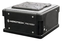
Figure 2: The Aerotech Pro-SV was designed for applications that need to precisely position a payload in the vertical direction.
Vertical lift
“Machine builders and system integrators are often faced with difficult design tradeoffs. In the case of a vertical lift stage, these tradeoffs often include precision, form factor, travel range and load capacity,” says Brian Fink, product manager at Aerotech. “It’s not uncommon to have to choose between one lift stage that offers high load capacity at the expense of precision and form factor, versus another lift stage that provides very high precision but has short travel and doesn’t carry a large load.”
Aerotech designed its Pro-SV linear lift stage to minimize these tradeoffs. Fink says the Pro-SV is an ideal solution for applications that need to precisely position a payload in the vertical direction, such as semiconductor manufacturing; test, measurement and inspection systems; and machinery for precision manufacturing (Figure 2).
“Sometimes referred to as elevation stages, vertical lift stages translate a carriage or tabletop that has a surface perpendicular to the direction of gravity. Unlike a traditional stage mounted vertically, a vertical lift stage is specifically designed to precisely position a user’s payload along a gravitational axis,” Fink says. “Because this type of stage lifts the payload from underneath, instead of from the side as with a traditional linear translation stage, the vertical lift stage provides clear, unrestricted access to the payload in both manufacturing and inspection processes. In cleanroom environments, especially common in semiconductor applications, the entirety of the stage is below the working plane, which helps to keep the customer’s workpiece as clean as possible.”
Fink says that a common problem associated with some lift stages is subpar geometric performance—straightness, pitch, roll and yaw. Pro-SV’s innovative solution uses anti-creep, crossed-roller bearings to support and guide the moving carriage in all directions. “Pro-SV is engineered for seamless integration into multi-axis stage platforms, motion systems and machines,” Fink says. “Directly coupled rotary encoder feedback is standard, and several optional high-resolution linear encoder additions exist for enhanced precision when operating with dual-loop feedback. When payload management safety is critical, Pro-SV can be configured with an absolute linear encoder, as well as a holding brake, to provide extra levels of protection against inadvertent damage to the payload.”
Also read: Power and compactness are the big trends in drive design
Payload management safety is important, Fink says, in applications with expensive components doing precision movement, such as inserting a sensor or probe into a reamed hole to measure the tolerances, or the testing and production of a heavy, expensive payload, such as a component of a satellite or an optical assembly that could be damaged with an uncontrolled descent or crash into nearby equipment. “Adding a fail-safe holding brake mitigates these risks,” Fink says. “If the stage were to lose power due to a controller fault or a power outage, the fail-safe brake would automatically engage when power is lost, thereby locking the vertical lift stage at its current position, protecting the payload from damage.
“The linear encoder has the benefit of bringing a direct position measurement closer to the customer’s work piece, further improving the stage’s positioning performance,” Fink says. The use of an absolute encoder eliminates the need to perform a homing cycle upon initialization. “This contributes to more efficient customer process cycle times and further reduces the risk of avoidable crash conditions,” Fink says.
The Pro-SV does not use a wedge design to achieve vertical motion like other lift stages. It uses a vertically oriented ball screw with an integral motor. “The drive mechanism acts directly on the vertically translating carriage. The absence of a wedge and the associated drive couplings is the primary contributing factor to Pro-SV’s compact form factor,” Fink says. With a drive mechanism that acts directly on the moving carriage, it provides a long range of vertical motion and the shortest possible overall height. “The short overall height aids in minimizing the user’s work-point height, thus minimizing the Abbe offset and contributing to greater overall precision,” Fink says.
The Pro-SV has three models that balance travel range, payload capacity and size. The Pro165SV is the smallest model with 20 mm of vertical travel with a 165-mm footprint, a minimum height of 95 mm and rated for 20-kg payload. The mid-size model, Pro190SV, offers 33 mm of vertical travel with a 190-mm footprint, a minimum height of 130 mm and rated for a 40-kg payload. The Pro225SV is ideal for the largest payloads up to 60 kg with 50 mm of vertical travel, a 225-mm footprint and a minimum height of 155 mm.
Only minimal maintenance is needed, Fink says, with no drive belts, gears or flex-couplings between the motor and drive screw. All Pro-SV stages are available with Aerotech’s ThermoComp, an integrated temperature compensation solution for dependable positioning performance in thermal disturbances.
The precision-ground ball screw provides smooth and reliable linear translation, Fink says, with a mechanical advantage. “Compared to a leadscrew, a ball screw is smoother and exhibits lower frictional characteristics, resulting in superior positioning accuracy and repeatability. And unlike other drive mechanisms, such as a belt-and-pulley arrangement or a gear drive, the precision-ground ball screw is able to transmit high forces at reasonable speeds, with zero cogging and minimal backlash, contributing to superior motion performance characteristics and helping users to optimize their processes.”
The slotless, cog-free torque motor was specifically engineered to mount directly to the drive screw. With no mechanical couplings, belts or gears that could wear, slip or fail, this arrangement provides consistent performance over a long service life, Fink says.
“Pro-SV’s crossed-roller bearings constrain the stage to move only in the vertical direction. The bearings’ excellent stiffness maximizes the stage’s geometric performance by reducing off-axis errors, resulting in superior straightness, pitch, roll and yaw motion characteristics,” Fink says.
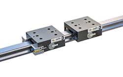
Figure 3: The Nexen rail brake was designed for E-stop applications that need to hold a payload or stop the payload.
Braking safe
Justin Hillukka, lead engineer for power transmission and custom products at Nexen Group, says for a few years, the industry has been shifting to more defined machine safety requirements, standardizing more robust methods of machinery safety. In October 2020, Nexen Group launched the full NexSafe product family of functional safety certified rail brakes, rod locks and servo brakes.
The rail brake is a spring-engaged, pneumatically released product, designed to mount on linear guide rails to hold or stop a payload. “The internal springs apply a force to a wedge, which multiplies the force and in turn applies the force to the friction facing. There is a spring, wedge, facing on each side of the brake to clamp from each side, further multiplying the holding force,” Hillukka says. “Air pressure is applied to multiple internal air chambers to release the clamping load.” The two actuators apply braking force to each side of the profile guide rail and can be fitted with sensor backpacks to monitor the state of the brake.
The actuation springs for the rail brakes are designed to ensure full force throughout the duration of the product life cycle, Hillukka says. “The driving wedge that transmits the actuation force from the springs into the facing is a through hardened bearing steel. The facing is machined from a metal alloy that has excellent frictional properties, low wear rate and is designed to have minimal effect on the mating rail,” he adds. A profile guide rail is used with linear bearing blocks, which roll and provide rigid and low-friction guiding. “The payload is bolted to the bearing blocks and typically, the rail brake is mounted between two bearing blocks to provide rigid holding,” Hillukka says.
The Nexen rail brake was designed for linear applications that need to hold the payload or stop the payload in an e-stop application (Figure 3). “Typically, for linear applications, a machine would utilize profile guide rails for bearing support, and the Nexen rail brake can be designed in to fit on most manufacturers’ rails,” Hillukka says. “It has been tested at different payload levels and fall speeds for e-stopping a payload and statically cycled to 2 million engagement cycles on a profile rail.” It can be used in low- and high-risk applications. The rail brake has multiple actuator springs, which can be removed for a lower release pressure application. The friction facings can be specified to match almost every manufacturers’ rail on the market, Hillukka says.
Nexen worked with Intertek, a third-party certified body, to review the rail brake product, achieving a functional safety certification. The rail brake is certified to meet applications of performance levels A through E and category levels B through 4, per ISO 13849-1. “Nexen worked with Intertek to review and ensure documentation and processes were set in place for material procurement and sourcing, supplier management, incoming inspections, factory acceptance testing, the management of functional safety, design and validation documentation and conformity to external standards,” Hillukka says.
Safety applications require the safety mechanism to be default to lock or safe position. “This means the brake designed to hold the payload must move to a locked position if there is an error or fault,” Hillukka says.
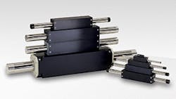
Figure 4: Nippon Pulse’s linear shaft motor has a coil surrounding the shaft, which provides 360 degrees of flux and high force-to-size ratios.
Tubular design
For machines requiring precise linear actuation, linear shaft motors offer a simple design, says Bob White, technical sales manager at Nippon Pulse. Nippon Pulse’s linear shaft motor is a tubular linear servo motor design, and the technology serves as an alternative to conventional iron core or U-channel linear motor actuators, White says.
“The linear shaft motor, iron core and U-channel designs consist of a forcer element made up of motor windings and a magnet way or track. The linear shaft motor and U-channel designs are ironless and thus have zero cogging. The linear shaft motor incorporates magnetic disks inside the shaft, as opposed to flat magnets on both iron core and U-channel designs,” White says.
The direct drive servo solution is ideal for applications requiring high speed, quick acceleration and high forces within limited space constraints. “OEMs can easily design the linear shaft motor into their machine mechanics to minimize space and eliminate conventional mechanical transmission elements, such as gear boxes, ball screws, belts and pulleys and other transmission devices that are prone to wear and require frequent maintenance,” White says. “A direct drive linear motor is designed to provide high force across a wide speed range, which means there is no need for additional mechanical levers.”
The innovation in Nippon Pulse’s linear shaft motor is found in the coil surrounding the shaft, which provides 360° flux and high force-to-size ratios (Figure 4). The design includes a forcer (coils) with a non-critical airgap, and a tubular stainless-steel shaft containing high energy magnets. “The motor coils surround the magnets, thus achieving a complete 360° of flux to produce force,” White says. This makes linear shaft motors more efficient, he adds.
“The forcer completely surrounds the shaft, which is the reason there is 360° of flux production,” White says. “The other aspect is the air gap is noncritical, meaning it can tolerate variations in the gap as the forcer traverses down the shaft—if the shaft is off-center, the average flux production remains the same.” The forcer can travel along the shaft without the need for the shaft to be centered precisely, as force can be developed around the shaft. Precision placement of the shaft within the coils is not required, he adds.
Higher-efficiency designs can reduce the losses associated with electrical systems. “With reduced losses, the motor can be made smaller, since it does not need to dissipate as much heat. Efficient designs allow more power to be packed in a smaller space. This can help the machine designer to reduce the footprint of the machine,” White says.
The motor is powered through a standard three-phase brushless dc servo drive. Various feedback elements, including optical and magnetic encoders, can be used to provide closed-loop positioning. “The motor is also a direct drive solution, meaning the load is connected directly to the moving element. Direct drive solutions are more robust, operate at higher bandwidths and in turn, help customers improve productivity,” White says.
This technology is for any machine that requires precision motion with fast move and settle times. “The fact that the load is directly coupled to the forcer—direct drive solution—can eliminate compliance. Compliance causes delays in the system, which reduces system bandwidth. By eliminating compliance with a direct drive system, machines can run at higher system bandwidths. This translates it to faster index times, which allow production of more widgets an hour—increasing machine productivity,” White says.
Figure 5: Ewellix Liftkit telescopic vertical column and the Slidekit horizontal slide is being used in collaborative robot applications.
Cobot movement
“Indeed the underlying theme of smart products affects linear motion products, as well. In order to reach complete control of the equipment and implement advanced features, such as predictive maintenance or real-time performance optimization, sensors and electronics need to be integrated on linear motion systems,” says Will Morris, category manager of Allied Electronics & Automation, a distributor for Ewellix, which is actively working to launch a smart linear actuator—a new, intelligent platform that is flexible and connected, Morris says. “With this offering we are enabling customers—OEMs and end users—to unlock a new world of benefits like increased productivity, higher uptime and lower total cost of ownership,” he adds.
Over time, electromechanical actuators may have a lower cost of ownership. They can cost more than pneumatic or hydraulic cylinders upfront, Morris says, but they can see savings in total system installation cost. They do not require all the pressure generation equipment that’s needed for hydraulic or pneumatic systems. “Electromechanical actuators are also simpler to install than fluid-powered cylinders,” Morris says. They have better long-term energy efficiency and less maintenance, he adds.
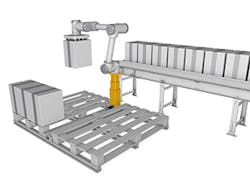
Ewellix’s electromechanical actuator technology is already incorporated into height adjustable pillars and into slides that increase the capability and versatility of robotic systems via its Liftkit telescopic vertical column and the Slidekit horizontal slide (Figure 5). “Most collaborative robots operate from a fixed base, which restricts the space over which they can operate. That limits their ability to take on certain tasks, such as transporting objects across longer distances, or handling at height,” Morris says. “To overcome this, users are now installing their cobots on moving platforms, powered by electromechanical actuators. Vertical pillars using a telescopic design can be floor- or ceiling-mounted to allow a cobot to work at any required height. That capability is particularly useful in pallet-stacking applications, which may require the robot to work anywhere from floor level to a height of 2 m or more.”
Cobots can also move along a packaging line to work at different stations or move automatically between machines by way of horizontal linear modules. The inherent precision and rigidity of electromechanical actuators ensures the robot is stable and properly positioned for every task, Morris says.
Liftkit has positioning accuracy of +/- 1 mm, which is sufficient for palletizing or packaging, Morris says. “At full Liftkit extension, the lateral deflection of the plate connecting the top of the Liftkit to the base of the cobot, considering the maximum extension of the cobot—typically in the range of 1,200 mm—and the cobot payload—usually 5 kg to 15 kg—will remain in the range of 3 mm,” Morris says. Glide pads in between the telescopic extrusions ensure Liftkit’s rigidity, he adds. The Slidekit has a higher positioning accuracy of +/- 0.05 mm because of the high-precision ball screw drive and preloaded profile rail guide system.
As part of a set of plug-and-play solutions, Ewellix worked with leading cobot manufacturers to develop the Liftkit and the Slidekit, Morris says. Both are supplied with a mechanical interface plate for quick and secure cobot mounting. The kits also include a dedicated software interface that can incorporate new motion capabilities in about 30 minutes typically, Morris says. Ewellix provides plug-in and operating instructions. “Liftkit requires a first-time homing operation. Then, the customer program its motion profiles through the robot teach pendant and is ready to go,” Morris adds.
Figure 6: The Bosch Rexroth Smart Function Kit is ideal for Cartesian and gantry applications.
Flexible system solution
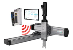
Customers want fast intuitive tools to automate and speed the process of sizing, selecting, specifying and obtaining CAD models for use in their designs of linear motion products, says Richard Vaughn, automation engineering manager at Bosch Rexroth. Customers also want automated commissioning, drag-and-drop programming, data collection abilities and preventative maintenance analysis as part of a standard package, he adds. In May, Bosch Rexroth launched its full package, the Smart Function Kit for Handling with linear axes mechanics including servo motors, servo drives, integrated control system and configurable HMI. The mechatronic positioning and handling solution moves work pieces within a defined space, combining preselected mechanical, electrical and software components into various kits. “Rexroth linear axes are combined with innovative control technology and software to create a perfectly tailored system solution,” Vaughn says.
“The products were designed around the concept that Bosch Rexroth motion components should be fast and easy to design, procure and use in a modern manufacturing facility,” Vaughn says. “The product range will ultimately reduce the time and effort required to specify, order and implement while offering the benefits of embedded drag-and-drop programming and data capture capabilities.”
The Smart Function Kit is ideal for Cartesian and gantry applications for pick-and-place in logistics, machine assembly, packaging technology or in assembly processes (Figure 6). “Cartesian motion systems are becoming increasingly popular with customers that exhibit various levels of experience. Typically, motion on a CMS would be handled by senior level or higher controls engineers. With ever-increasing demands on these types of engineers, it is becoming difficult for them to break away from expert-level projects to help develop novice-level applications,” Vaughn says. “We are seeing more demand for simple and intuitive Cartesian systems used by personnel lacking expert programming knowledge.” He adds that Cartesian systems are suitable for a wide range of applications, large and small. “Small laboratory-type equipment may be an opportunity for a CMS, in which the user is completely self-sufficient from start to finish,” Vaughn says. “Projects utilizing larger-scale equipment can benefit also by enabling the mechanical engineer or line technician to produce motion without solely relying on a programing expert.”
The solution uses LinSelect, an online sizing and selection tool, to accurately and intuitively size products to fit the application. The software will design a solution with all the necessary components, including all axes of motion, connection bracketry, a fully designed and built cable management system, plus perfectly matched servo motors, drives and cables. “The preinstalled plug-and-play software allows for fast intuitive commissioning and process configuration,” Vaughn says. “Once delivered, the embedded software wizard handles the commissioning.” This ensures a short time to market and quick production start, he adds.
Users do not need to identify obscure component parameters, as the system already has those stored specifications. “Programming is simple drag-and-drop style, using the pre-built library of motion steps and intuitive parameter inputs,” Vaughn says. The system also includes processing tools for data collection and process step validation, making this task very easy for novice users. “Prebuilt, easy-to-commission and perfectly matched components take the user from delivery to real, usable motion in record time,” Vaughn says.
The system can be tailored to meet many individual application needs. “The sizing and selection offer a wide range of component capacities within the overall product line. The customer is not relegated to a one-size-fits-all approach; rather, they receive only as much as they need for a specific application,” Vaughn says. The software can build motion profiles from an array of pre-defined program function blocks.
The system currently has more than 25 unique combinations of axes for the most common Cartesian motion system applications.
