How a 3D scanner and robot replace a complex manual trim process
An aircraft manufacturer was concerned about having skilled personnel available for a time-consuming process step. The problem had two parts, retiring skilled workers and a legacy aircraft design. Although the aircraft was within tolerance, it had significant variations in final dimensions.
Properly trimming the doors and hatches is a skill that develops over time, and, as the workers retire, there is concern that these skills would be lost. It is one of the reasons RedViking was asked to provide a solution. Either new workers could be trained, or automation could make the process easier and much faster.
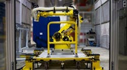
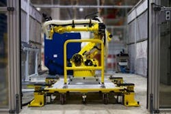
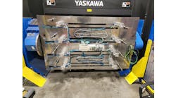
Figure 1: This robotic trim cell replaced a time-consuming, manual trim and drill process with a precision automation system, reducing hours per assembly by 85%.
(Source: RedViking)
The problem was that the customer had aircraft to build on a tight schedule, and, due to the time period when they were designed, those aircraft had quite a bit of variance, notes Mark Sobkow, vice president of manufacturing solutions at RedViking (www.redviking.com), a manufacturing and test solutions builder headquartered in Plymouth, Michigan. RedViking had previously demonstrated its capabilities on end-of-line component and transmission testers for this customer, but the measurement and trim project was a completely new undertaking. "The challenge was to fit hatches and doors to this aircraft,” he says. “Each opening was different, so hand working of the components was necessary. The new system was designed to digitally measure the openings in the aircraft to be covered. We can then use that data to figure out how to automatically cut and shape the doors and hatches to fit (Figure 1)."
This custom system reduced the process time from days to less than a day, explains Sobkow, describing the customer’s former measurement and trim process. "The workers would fit the hatch to the airframe and chalk the part to that particular aircraft. They would then remove the hatch and use hand tools to trim and drill the part to fit. Fit, measure, mark, trim, repeat. The workers were accomplished and made a good product, but it took a significant amount of time."
Start oversize and trim many times
The aircraft had so much variance that all openings are different; no two doors or hatches are alike. Because of this, doors and hatches are made oversize and then manually trimmed to fit.
"The variations were mostly due to when this mid-size, passenger-capable aircraft was designed in the early 70s," says Sobkow. "The prints were very old, and it's difficult to make engineering changes to update the design to technologies of the 21st century. It was easier to work with the design as is and create the automated trim cell."
The manual trimming process required skills to do it properly, some tribal knowledge, and some old prints. "The goal was gap tolerance, which was a big issue in the past," notes Sobkow. "It's similar to how the doors of an automobile were a huge problem in the past. The door must close properly with a consistent gap and not leak."
Automotive manufacturers fixed the gap in the early years by hammering completed vehicles with 2-by-4-inch lumber wrapped with carpet. Today, automotive solves the gap-consistency problem using computer design models and automation. This technology brought the overall variance down so that any door would fit any car it was designed for.
You don't have the opportunity to do that with an aircraft. In some ways, it's like rebuilding a 1970s vintage car. In addition, with aircraft, you cannot just change a dimension or tolerance. That would involve many regulations and requirements that need to be followed and tested, so the industry tends not to change their design.”
Find and measure the opening
Today, a portable metrology cart is wheeled onto the assembly floor and manually positioned near the aircraft to measure an aperture. A 3D laser radar system is then used to scan the opening. A mast is used to lift the laser radar up 20 to 25 feet in the air to scan the area of interest.
The cart and mast had to be made rigid and to simplify metrology cart positioning, a couple of tooling balls are used to find a relative position in space on the aircraft. Locating the cart within about 2 inches of a nominal position was all that was necessary for it to find the aircraft-mounted tooling balls and measure the opening.
A laser radar scan then creates point cloud data of the opening. In addition to using the software internal to the scanner, RedViking wrote a custom algorithm to translate the point cloud data to a usable robot trim path and hole-location code. This data is sent to the robot to adjust the trim routine for a particular part. It's the conversion of this point cloud to usable robot code that brought this project to life.
The tooling and offset trim path is then used to modify the part. The cloud data is nominal data, and additional manual offset is provided for each trim edge and hole as well, depending on the gap tolerance needed.
We found when setting up the parts with all the system variation that we are maybe ten thousandths of an inch from where we need to be, but the error is very repeatable. This enabled us to apply an offset to cancel out the error. It is also used to adjust the gap between the hatch and the skin of the aircraft.
Another feature of the system is that the measurement point cloud data and trim path are saved in a database. By entering the part number and serial number, the stored data can be used to trim a replacement hatch if needed. This eliminates the need to hand trim the part in the field.
Robots are not very accurate
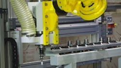
Figure 2: Careful design of the robot tool changer and tight manufacturing tolerances helped to improved overall system accuracy.
(Source: RedViking)
Overcoming the accuracy of the system was a big focus of the hardware and software design. The laser radar system, robot, and tooling all affect the accuracy, and the tolerance stack up in this system was significant. "There is a lot of stack up, and the design goal and much of what we did was to eliminate it," notes Sobkow. "While the laser radar had a tolerance of a couple of thousandths, adding in variations in the robot accuracy and repeatability, aircraft datum points, and part fixture caused significant error stack up that needed to be addressed."
The off-the-shelf robot was the biggest inaccuracy in the system. While the robot repeatability is excellent, it doesn't go to the same position every time due to the trim path variations required for each part. This highlighted the robot's accuracy error. It also holds a large router in its end effector. The use of a large robot provides a rigid platform, but, even with an in-cell calibration unit and special calibration, it was a challenge.
The robot also interfaces to a tool changer to select the proper tooling for the trim or drilling step of the process (Figure 2). The tool changer provided an opportunity to reduce errors. The spindles were designed to have very little runout and tight tolerances to introduce as little error as possible with the cutter.
Precise fixtures and carts
A proper trim of the part requires much more than just an accurate measurement and robot path. To perform the trim, the oversized part is placed in a precision tooling fixture that RedViking designed. This fixture has very tight tolerances to mate with the part and present it to the robot the same way every time. The fixtured part, mounted on a mobile cart, is precisely docked in front of the robot, and the operator initiates the trim cycle.
The accuracy of the system hardware is precise by design. Originally the plan was to find the part in space using probes. However, using RedViking's experience with end of line testers, gauges, and geometric dimensioning and tolerancing (GD&T), we were able to engineer and build a cart to mechanically fixture the part in a very repeatable and accurate fashion.
The oversize edges were not used to position the part. Instead, internal features that were repeatable as well were used. We met our goal of holding the part and presenting it the robot repeatably, within a couple thousandths of an inch, every time. The laser radar found the datum on the aircraft and the cart fixture tooling located to the part's matching datum.
Since there were multiple carts to stage different parts, precision tooling was also used to repeatably locate and clamp a cart to the robot assembly. Repeatable cart locating allowed a total of four carts and six unique parts to all work with a single trim cell robot.
Additional automation
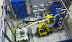
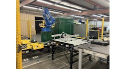
Figure 3: In addition to the cart and robot, significant safety guarding, debris recovery and related automation was needed in this turnkey automation cell.
(Source: RedViking)
The system includes more than just the laser scanner, robot, and tooling. Outside of the trimming and drilling processes, there is additional automation involving hydraulic, pneumatic, and air-handler systems to make the cell work. This includes control of safety doors, emergency stop, and other safety hardware in the system. It's a fully automated robot cell that RedViking designed, built, and programmed (Figure 3).
The end user wanted the operator to hit only one button to start the process. To do that, a level of automation is required to determine the cart is present, clamp it, locate it, and then run a trim and drill sequence.
Error proofing included using an electrical harness to plug the cart into the trim cell to identify it. There is also a work order that the operator will input into the test-cell HMI including part serial number and aircraft number.
ALSO READ: The keys to robot selection, safety and collaboration
Airplane needed for development
Installation was another challenge. This system is a custom, one-off process, and the customer didn't give us an aircraft to scan and a bunch of parts to trim and drill. The system needed to be developed in process on the customer site during manufacture of the aircraft.
Development required careful coordination with our customer. We had to stop the process, and all personnel needed to exit the aircraft before scanning and opening. With the aircraft sitting on shocks and wheels, it only took one person to shake the plane enough to cause laser-radar scanning errors.
Not only did RedViking have to develop the system on-the-fly, but the material that needed to be trimmed and drilled was also proprietary. Tool life was touch and go, and we didn't know wear and tear. We still don't know what the raw material is. During the design phase, this made it difficult to select cutting tools, let alone cut speeds and feeds. Even dealing with the dust required development work.
The resulting finish of the trimmed and drilled part needed to be developed, as well. Improper cutting and drilling cause burrs and other imperfections on the part. The robot needed to be able to match the fine, detailed quality of finish that was originally being done by hand over several days. In the end, tooling and cutter selection, tool life, along with determining the optimal number of trim passes minimized finish issues. When the part leaves the robot trim cell, the edges are touched up with paint, and it’s ready to go on the aircraft. The result is a well-fitting, air-tight piece of art.
Approaching CNC machine accuracy using a robot is not something available out of the box. In this automated aircraft measure and trim cell, accuracy errors are minimized wherever possible and measurement devices, robot paths, and fixture tooling are carefully selected, designed, and programmed.
It was a significant amount of work and time for both us and our customer, but it quickly paid dividends. We’ve been adding capabilities over time, and the customer continues to add more parts to the system. The system has been functional for the past year, and the customer is very happy with the results. The huge return of investment from the reduction in labor costs has already paid for the system.
Sponsored Recommendations
Latest from Robotics

Leaders relevant to this article:
