From e-stops to collaborative robots: How automation technology transforms industrial safety
When it comes to automation, safety is the first priority when people need to interact with the equipment.
Over the years, safety devices have changed a lot. In the early days of automation, e-stops and door switches were pretty much all that we had to work with. In the control cabinet, an electromechanical relay provided the means of interrupting the control voltage to isolate the driven devices from the source of power. The solution was simple but rife with risk of failure.
Safety circuits were a single circuit chain of devices powering a control relay. That control relay would permit power to output devices, as long as the chain was intact. With a single circuit, any one of the devices in the chain could fail, and the circuit was no longer safe. Contacts wear out over time and could fuse in the closed position with the user none the wiser.
The same holds true for the control relay. Over time, the springs in the relay get weaker and could allow the contacts on the relay to remain closed after the power is removed from the coil.
Safety has changed a lot, and the technology behind that is driving how we approach automation. Dedicated safety relays with dual-redundant circuits are the standard by which we design our circuits. Built-in to the safety relay are monitoring algorithms that watch for small variations in the twin circuits to capture when a device, or subcomponent of that device, is failing and annunciate accordingly.
Devices used in a safety circuit have advanced with the technology, and all the major manufacturers offer a wide variety of components to cover pretty much anything you might want to protect.
It is the availability of such a broad spectrum of safety devices that has dictated the type of automation that can be deployed safely. The manufacturing environment has changed dramatically in just a few short years, and the proliferation of collaborative robots has made the interaction between people and machine into a close-quarters dance with increased risk but for the use of sophisticated safety systems and devices.
The choice of components breaks down into categories based on three questions:
How do we sense the danger?
How do we stop the action?
What makes that decision?
Sensing a risk starts with assuming that a human is going to be present in close proximity to the operational envelope of the machine. The goal is to determine how close the person is and alter the behavior of the machine based on the real or perceived risk at that distance.
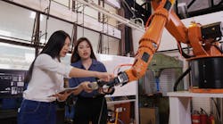
For example, a collaborative robot (cobot) is deemed collaborative because it can operate in close proximity to a person without the need for a physical barrier to isolate one from the other. Some of the main considerations in determining whether it’s collaborative are the size, speed and mass of the robot.
A small robot, not much bigger than a person, with a payload of 2 kg or 5 kg, can’t move very far or very fast and, with given limitations, can work in close proximity to a person.
To limit the risk of working in close proximity with this small robot, some safety features are employed. The joints in the robot include technology to sense the resistance to movement. If the robot bumps into something, like a person, the opposition to the intended movement is detected and corrective action is taken. Depending on the opposing force, it could slow down the action or actually stop and move in the opposite direction before coming to a stop.
Another safety feature is pressure-sensitive safety skin. This technology senses the state of the “skin” of the robot when in an untouched state and then looks for a change due to a foreign object pressing on the skin.
Yet another safety feature is a loosely fit guard on the end of arm tool that is easily knocked off with little pressure applied. A safety switch on the guard is active as long as the guard is in place and immediately cuts off the safety circuit if the guard is displaced.
While these techniques are effective for a small, slower-moving robot, the risks are greatly raised if the robot is larger and faster with a larger payload capacity. For these applications, additional features must be added. It is no longer enough to just sense the bumping of a person with the robot.
The approach to automation is to split the function into collaborative and non-collaborative mode. A combination of light curtains and area scanners are deployed to extend the operating envelope outward to a point where higher-speed motion can happen in a non-collaborative mode. If a person or object is detected to breach that larger area, the robot automatically slows down to a collaborative behavior where all the other sensing methods can be safely employed. In this way, an industrial robot can be employed in a less-than-fully-enclosed envelope with the additional safeguards in place to prevent high-speed motion when necessary.
The preceding scenarios elaborated on methods employed to sense a risk. The control system must then utilize methods to reduce or stop motion when needed.
A number of safe motion features can be employed in this situation. While not a complete list, here are some of the means by which motion can be affected in a safety-triggered event.
Safe torque off (STO) is the base motion safety function whereby the drive is rendered to a no-torque state. This means, regardless of a potential command, the output stage of the drive is completely disabled electrically.
Safe stop or safe stop emergency describes two other reactions to a safety situation. In a safe stop, the motor is ramped down to zero speed in a controlled manner before the STO is enacted. For a safe stop emergency, the system can either deploy a safe stop—ramp to zero—or a safe torque off, depending on the device being controlled.
Other safety motion methods include a safety limited speed (SLS), which forces motion to a specific slow speed, and safety maximum speed (SMS), where the motion is limited to speed less than full speed but not a specific slow speed.
The safe torque off feature has revolutionized machine design because it can be used to safely isolate high-voltage presence on a machine during an e-stop condition. With the output stage of the drive disabled, power to a control system can remain on, rather than a complete power-down lockout of the mains to a control cabinet.
Since the means of power isolation is built-in to the drive, there is no need for individual safety contactors for each drive.
Sensing a risk and bringing the motion to a safe condition must be done in a way that is proven, reliable and repeatable. While a safety relay might be employed to make these decisions, more complicated machines might dictate the employment of a dedicated safety processor to make the critical responses.
The primary difference between a safety relay and a safety processor is the ability to add logic to create groups of safety devices and associated safety outputs.
A safety relay would simply monitor one or more safety channels and apply or remove control power collectively to the safety outputs of the relay. Each safety channel could be one or more safety devices in series with each other.
There is no way to individually detect or monitor devices by means of the safety relay. Each safety input device would have to have a third contact that is wired to a programmable controller to provide a status that can be displayed on an operator station.
With a safety controller, each safety input is connected to its own input on the controller. Status of the dual channels of each device is monitored by the controller, and the status of that device can be provided to the programmable controller operating the machine to provide status to the operator station without the need to provide physical wiring to an input card on the programmable logic controller (PLC).
Additionally, a safety controller can have multiple outputs that can be used individually or in groups, depending on the user application in the safety controller.
Safety controllers tend to be programmed pictorially using gate logic and with built-in features that can be selected by telling the safety controller what type of device is connected to each input on the controller. Since the safety controller is independent of the controller that runs the rest of the machine, it is making decisions on a fixed number of control points and is not impacted by the scan time of the main machine-control algorithm.
The type and availability of safety devices has opened up the types of automation that can be deployed in manufacturing and reduced the traditional operating footprint that hard-guarding dictated. Systems are safer with a higher degree of confidence, so humans and machines can interact in an ever smaller envelope.


