By N. Lewis Bodden
I enjoy developing new and innovative control system concepts. The most challenging projects involve physical measurement because there are many things to consider: total length, resolution, response speed, mounting and more. The electrical and software considerations are the easy ones compared to the mechanical factors.
Most applications require that a measurement be taken with a zero starting point and account for movement in both directions. A quad-phase or quadrature encoder fulfills those requirements. It has two signals 90° out of phase. Most of them are optical. Mounted inside the device is a wheel with a pattern of boxes going around the wheel. The number of boxes determines the resolution.
A quad-phase encoder connected to a high-speed counter is a good solution. Most brands of PLCs have high-speed counter modules capable of doing the job. Zero the counter at one point, move to the desired position and stop.
Simple, right? Well, there are a few things to overcome. The first problem is to get it to stop at the right place, as they say on The Price is Right, "without going over."Telling it to stop does not cause it to stop immediately. Inertia causes a big problem. An early cut-off method can be used to compensate, effecting a stop at the desired point.
IIS in Pattison, Texas, manufactured insulated construction panels on steel frames in 2006-2007. The buildings were designed for use in cold climates as everything from living quarters to doghouses. IIS manufactured Styrofoam panels 4 in. thick by 4 ft wide with sheet metal on the top and bottom. The sheet metal is glued to the Styrofoam to make an insulated construction panel and extruded in a continuous process. Twenty ft from the extruder, an assembly clamps the manufactured panel and cuts it with a saw. It's easy enough to mount an encoder on the saw assembly to measure the length of the panel as it goes by. A list of panel lengths and quantities are entered using the HMI.
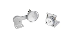
We bought the encoder as an assembly complete with a rubber wheel, mounting bracket and cable. It was easy to mount with Unistrut metal framing. The encoder was wired to a Rockwell Automation Allen-Bradley CompactLogix high-speed counter module. No external power supply is required.
Read the encoder signal and compare the length measured to the setpoint length less the early-cut-off length—the distance traveled until the clamp is fully engaged, plus the width of the saw blade. When the length measured exceeds the desired net length, then initiate the clamping mechanism and make the cut. When the cut is finished, release the clamping mechanism and move the saw assembly backward to get ready for the next operation. A check is made before cutting to verify that the length of the piece is within tolerance. Records of each cut were collected into Excel spreadsheets on an existing PC via an Ethernet connection, and errors were flagged.
Accounting for the width of the saw blade can be done in one of two ways. It can be added to the calculations for the early cut-off. The preferred method is to preload the width of the saw blade as a negative value when the counter is reset. It requires less math and the position of the cut is simply the counter display in the desired units.
When the saw assembly was moved backward after each cut, it would crash into the stop and bounce all around like a train wreck. This would cause the encoder wheel to come off the panel and throw the count off. It took some adjusting of the air-powered piston's valves to get it right. It had to be fast enough to move back for the next cut and still be able to slow down before hitting the stop.
The encoder path must be kept free of the cuttings from the saw. A small brush mounted in front of the encoder sweeps the cuttings to the side. It also must press against the panel with enough force to keep it from slipping. Originally there was no support of the panel below the encoder. The span across the saw assembly was about 5 ft. The encoder would rise and fall to near the limit of the spring on the encoder arm. We built platforms below the panel's path and used a pair of rollers to hold down the panel as it passed through the saw assembly.
N. Lewis Bodden is a control systems consultant in Houston, with 35 years of practical experience in system integration and control system design.