The image on the left shows a good image of a ramen packet. The image on the right has the same ramen packet at a 45° orientation. The polarizing effect is lost when certain materials are oriented 45°, and it is impossible to know without testing.

Common pitfalls in machine vision lighting

June 18, 2024
How to plan in the design phase to avoid bad project scope
Every so often, machine-vision-lighting evaluations end in the worst-case scenario for a customer. They spend weeks working with an integrator, going back and forth between updating information about the application and then revising the lighting solution until both sides end up in a meeting and conclude that the application isn’t feasible.
 
We tend to fall into this scenario when engineers have misconceptions and assumptions about machine vision, which can have major consequences for delaying project completion, if not terminating the project entirely.
 
 
These misconceptions can be broken into five general categories:
  1. when to consider vision inspections
  2. bad project scope
  3. testing samples/conditions
  4. previous application knowledge
  5. seeing vs. detecting defects.
Recognizing these bad assumptions can help avoid the worst-case scenarios: wasting time on a project that was impossible from the start, delaying a project because of a costly redesign after the machine is built or delivering a system to a customer that never ends up working the way they want it to.
 

When to consider vision inspections

 
The most consequential misconception is that vision inspection needs to be considered only after the machine is constructed. If you can’t use the best light for your application because of physical restrictions in the system design, the application will not have the best solution or can’t be solved. And this can be avoided by thinking about vision-system requirements from the start.
 

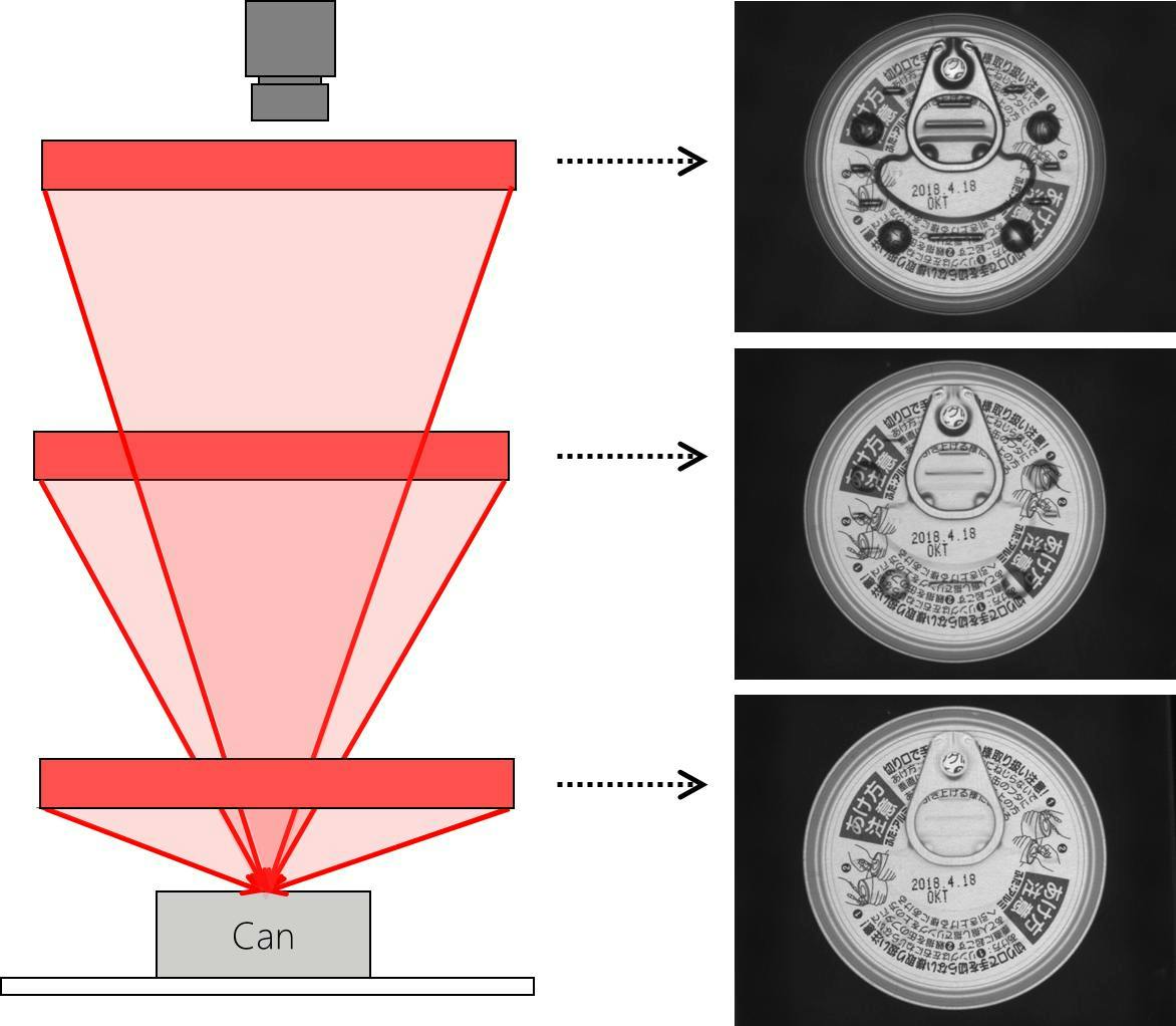
A major consideration is clearance for the lighting and camera. Light working distance (LWD) can make or break an application. Whether you need to install the light close to the object or further away to get the optimal image, if there are physical restrictions that prevent you from installing the light where it needs to be, that optimal image is impossible to capture (Figure 1).

 
If a machine is expected to run at a high speed, engineers should also factor in a brighter light into the system design, so the intensity is appropriate for the exposure time. And if ambient light causes unwanted glare, you can design a solution to prevent that glare from affecting the image, whether by using a faster shutter speed, using a bandpass filter or building a shroud into the design that removes the problem from the source.
 
Presenting the part to the camera is another key consideration, especially when inspecting some or all sides of the workpiece. It requires enough space for multiple cameras or designing the machine to move the part so all the relevant sides get inspected. The fixture that holds your workpiece can also prevent your light from illuminating the workpiece the way it needs to.
 
Engineers should factor in the physical requirements of a vision system early in the design phase to ensure that the necessary space and infrastructure for vision components are built in. Otherwise, they may need a costly redesign later in the project.
 

Bad project scope

 
The “bad” can have two meanings. First, the scope tries to accomplish too much beyond what is feasible. Or it means scope creep occurs, and the project's initial boundaries expand to include additional capabilities that complicate the vision system's requirements.
 
Engineers often assume a single vision system can inspect a lot more than is realistically possible. But, in many cases, demanding inspection of 100% of samples with 100% accuracy all the time is unfeasible. And other challenges arise when you try to inspect too much with a single camera, inspect with a field of view (FOV) that is too large or inspect an entire workpiece when it has too much variation in height or curvature.
 
Inspecting too much is not necessarily a problem with the number of inspection tasks. Problems start when engineers try to do too many difficult inspections with one camera. Especially when the FOV is larger, and the information being inspected is spread out. Breaking up inspection tasks between multiple cameras can often reduce the overall difficulty of an application.
 

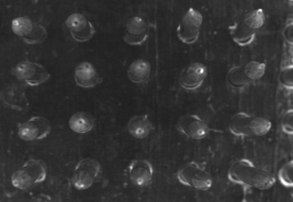
There is a similar nuance to inspecting with a field of view that is too large. Clear presence/absence applications can be easily solved with a flood light, but applications that require high-precision lighting and have larger FOV encounter difficulties. Many standard precision light form factors max out at 300 mm size, so the FOV must be smaller than that for the application to work. Having too many samples in one image is a similar problem. Optical components can change the viewing angle of samples depending on where they are in the image. To get a more consistent angle, you need to match the size of the FOV to the telecentric lens (Figure 2).

 
Finally, it is challenging to build a lighting setup that will accommodate all features on every workpiece when they have a lot of profile changes. This occurs often when inspecting multiple metal workpieces for scratches. The setup is so complex, it is more feasible to reduce the scope in one of several ways: design a setup for the most critical sample only, inspect only the flat surfaces or build a system with a robot and program multiple inspections that scan each type of workpiece.
 
Scope creep typically happens when different stakeholders add more inspection tasks to the original scope during the development phase. A simple application turns into an overcomplicated system that fails to meet any of the intended targets effectively. And then the project is abandoned without solving that initial problem.
 
Clear project boundaries will define tasks the application must perform to justify moving forward with the project. Keep a separate list of tasks that can be considered in the evaluation and will be added only if they are relatively easy changes to the must-have solution.
 

Testing samples/conditions

 
There are multiple bad assumptions concerning the samples and conditions used for testing. Engineers often test systems with a limited number of samples, leading to systems that perform well in the lab but fail in a live production environment, where there are way more variations in defects. It’s easy to draw the line between one good sample and one bad sample. But evaluations are more likely to find the best solution by testing with all potential variations of good samples, and all potential variations of bad samples, including borderline cases. By testing a large set of samples as they will appear when they reach an inspection stage, you ensure the system can handle real-world variability.
 

When a customer asks for a lighting recommendation based on a light’s lux or lumens, that tells us they have misconceptions about testing conditions. Because choosing the right light is not that straightforward. First, a light’s irradiance decreases as the LWD increases. Not only that, the irradiance uniformity over the area it illuminates changes size and shape, as well. Your sample’s characteristics also affect how it interacts with light. Dark samples absorb more light, while bright samples reflect more. Instead of choosing a light based on its intensity, the better approach is to first test that a light’s form factor, size and wavelength solve the application and then consult with the manufacturer about overdriving the light or purchasing a strobe-version of the light to get the brightness the application needs (Figure 3).

 
This is why it’s crucial to share as much information about your application as possible. You may assume a certain design feature isn’t relevant to the vision system, so you don’t need to share it with the manufacturer. But this is one situation where overcommunication doesn’t hurt. Unlike that worst-case scenario, it can help you avoid a prolonged evaluation phase because the lighting evaluation will be performed knowing all the restrictions from the start.
 

Previous application knowledge

 
Assuming a solution that was effective in one application will be directly transferrable to another similar application can lead to unexpected setbacks. Each application has unique characteristics and constraints—what worked in one scenario may not work in another without adjustments.
 
For example, a flat dome light with a polarizer can solve an application identifying a type of flavor packet. But in another similar application, looking at instant ramen packets for example, where the orientation of the packet is sometimes at a 45° angle, it is impossible to read the packet. If this reliability issue is only discovered after the system is delivered to a customer, the machine could end up collecting dust in a corner.
 
Engineers must avoid the "copy-paste" approach. If they ask a lighting manufacturer to recommend a light based on past applications, they should test the light before purchasing. This ensures a solution is tailored to the specific demands and conditions of the current application.
 

Seeing vs. detecting defects

 
Finally, the distinction between seeing and detecting defects is crucial. Just because a human can see a defect does not mean a machine vision system will detect it. Vision systems do not possess human judgment and rely entirely on contrast, patterns and predefined criteria to identify defects. We can look at a bruise on an apple and recognize that it is a bruise. On the other hand, machine vision can only recognize the bruise as discoloration on the apple. Whether it is a color variation that can pass inspection or a defect that must be filtered out, machines cannot see and judge as accurately as the application may demand.
 
While new technologies like artificial intelligence (AI) may close the gap, engineers must understand the limitations of technology. In doing so, they can develop systems that reliably detect what they are programmed to recognize, considering all variables that might affect performance.
 
When engineers go into applications with the right expectations, they are better prepared to define a realistic project scope and perform a robust evaluation that considers all the necessary factors before anything gets built. You see fewer projects scrapped and more finished systems delivered to customers who get exactly what they paid for.

About the Author

Lindsey Sullivan

Lindsey Sullivan spent eight years as an engineer evaluating machine vision applications in every industry. She started as a sales engineer at Keyence before moving to an application engineer at CCS America. In her current role as technical marketing manager, she is sharing her expertise so that industrial automation companies can design high-accuracy systems without troubleshooting lighting challenges after machines are built. Contact her at [email protected].

Sponsored Recommendations

2024 State of Technology Report: PLCs and PACs

Programmable logic controllers (PLCs) and programmable automation controllers (PACs) are the brains of the machine in many regards. They have evolved over the years.This new State...

2024 State of Technology Report: Packaging Equipment

Special considerations and requirements make packaging equipment an interesting vertical market unto itself. This new State of Technology Report from the editors of ...

High Sensitivity Accelerometers to Monitor Traffic and Railroad Vibration for Semiconductor Manufacturing

This paper examines highly sensitive piezoelectric sensors for precise vibration measurement which is critical in semiconductor production to prevent quality and yield issues....

Simulation for Automation Guide

How digital twin solutions are expanding the capabilities of plant engineers.