Have you ever been assigned to a machine and asked to rebuild it, recode it, re-something? It can be a daunting task, but if engineers look at everything as a system with parts, then reverse-engineering is possible on almost anything.
One might notice that reverse-engineering is, pretty much, just like design steps. The difference with reverse-engineering is there is one that works.
Get your subscription to Control Design’s daily newsletter.
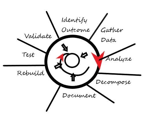
There are eight steps to a reverse-engineering process:
First, determine what the end goal is. Second, pull all the documentation. Third, analyze the current system and break it into sections and components. Next, document the system. After the functionality is understood, then the system may be rebuilt. At the end of every iteration, new or reengineered, the system must be tested and another analysis done. The first iteration is probably on paper, and part of the analysis would be: Do I build it? Is it buildable?
1. Gather existing documentation
Start by collecting any available documentation, such as piping and instrumentation diagrams (PIDs), electrical drawings and any other relevant records. Even outdated documents can provide valuable insights. The idea here is to get as much information as needed for power requirements, hardware requirements, mechanical requirements and software requirements.
2. Analyze the system
Examine the control system's components, including controllers, I/O modules and communication networks. Identify the inputs and outputs, and understand how they interact with each other. Determine what functionality and states make the machine work and what the inputs and outputs of each state/function is.
3. Disassemble the system
If possible, physically disassemble parts of the system to get a better understanding of its internal structure. This can help you identify the components and their connections. If not possible, decompose the system on paper with proof of concept and back up the reasoning. If it’s a rebuild from another generation, then compare equipment from old to new.
4. Document the findings
As you analyze and disassemble the system, document your findings meticulously. This includes noting the types of components, their configurations and any observed behaviors. This means sectioning off functionality and determining hardware, software, electrical, mechanical, safety, environmental and civil requirements.
5. Understand the functionality
Work from the outside in to determine the functionality of each algorithm and control logic. This might involve tracing signals and observing how the system responds to different inputs. If the system is decomposed far enough, then this should fall out. This is where state diagrams or cause-effect tables come into play.
6. Rebuild the system
Using the information gathered, attempt to rebuild the system either virtually or physically. This can help validate your understanding and ensure that all components are correctly identified and configured.
7. Test and validate
Finally, test the rebuilt system to ensure it operates as expected. Adjust the components and hardware as necessary based on the test results and based on what the expected outcome is.
8. Analyze again
The first step of the reengineering process is to determine or propose and outcome. Does the machine, or the design do what the proposal wanted? If so, then the iteration process is done. If not, then one must return to the documentation and figure out what is missing and start the analysis again.
Also, this is an example of when process is important. This is the time to use the analysis type of thoughts that you practice when you walk into a plant and walk down a line and your mind takes you to the pieces of equipment that you see, that makes the function happen. If you can write this out in pseudo-code and relate it to the specific hardware, then you can create a system or, in math terms, create an algorithm.
HMI
A good place to start on process is the human-machine interface (HMI). Most HMIs, when decomposed, will show you inputs, outputs, current state, desired state, control signals to cause a state, or in response to a state, and alarming. You can also find thresholds in the code for the HMIs and programmable logic controllers (PLCs).
With this kind of workflow, a project can go from a concept to something that is feasible that may be costed and then to being executed. A project manager could put a timeline on each of the phases and regulate goals. This idea is applicable for design or reverse-engineering.
If we compare it to making an algorithm, then an engineer could look at inputs and outputs to a function, or action vs. response. For instance, if steam is needed, then we must have water and a heat source. Inputs would be water, heat exchanger, temperature controller, temperature measurement with a transmitter to the PLC or to a temperature controller. The output is steam.
Thus, one can build a component list and pseudo-code based on the type of functionality a machine might need. The same thing may be done with an actuator. An air source is needed, an actuator, relays and or solenoids to trigger the response from the PLC or a push button for manual operations. The next question is whether it’s hydraulic, pneumatic or electric. This depends on the application.
This is system thinking. Once an engineer is in the habit of seeing, hearing and feeling the components of a function, then you start noticing how things are made. “Staring and comparing” is the name of the game. The purpose of this is to inspire thinking at a system level on a functionality that will result in a hardware list based on inputs and output. If the components, the trigger of the function and the expected result are known, then pseudo-code can be written. This is the path to a specification that can result in an actual build.


