Accuracy and surface quality are the goals of superior production processes. This is why machining companies invest a great deal of time and expense in tools, machine tools, controls with special functions and options, measuring technology and, of course, employee skills. Unfortunately, axis motors still receive very little attention in this arrangement, despite being a decisive factor in production quality.
When it comes to axis motors in machine tools, for example, torque ripple and the inertia ratio between the motor and the load are crucial factors, along with the maximum torque. These criteria have a direct effect on the quality of the workpiece to be manufactured. Axis motors for machine tools offer a balanced inertia ratio and very low torque ripple for exceptional machining results and dynamic motion control.
[javascriptSnippet ]
Withstanding disturbances
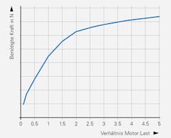
Figure 1: The graph demonstrates necessary load reversal force for a given position error (y axis) as a factor of the inertia ratio between the motor and the load (x axis).
(Source: Heidenhain)
By way of illustration, a lightweight trailer attached to a large, high-torque vehicle will introduce fewer disturbances into the entire system ω when exposed to wind gusts or road damage than will a heavy trailer pulled by a lightweight vehicle of the same torque. This is true even though the lighter trailer is obviously much more susceptible to these influences than the heavier one. For a machine tool, this means that the largest possible motor should be moving the lightest possible table in order to minimize the effect of disturbances on the entire system such as milling forces or vibrations arising at the table.
Unfortunately, if there is a significant difference between the inertias of the motor and the load, it is also necessary to lower the loop gains. Lowering the loop gains leads to lower rigidity, meaning that the entire system reacts more strongly to load disturbances, for example, from milling forces or vibrations.
For a machine tool, a balanced inertia ratio between the motor and the load should therefore be selected. A balanced ratio provides the amount of rigidity needed to make the entire system insusceptible to external influences exerted on the load, meaning that these influences have no effect on the machining result, and, at the same time, making it possible to work with high loop gains. In other words, the trailer and the vehicle pulling it should be correctly matched to each other.
The right dynamics
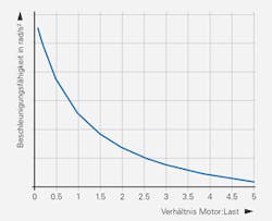
Figure 2: The graph demonstrates the acceleration capability of a motor (y axis) as a factor of the inertia ratio between the motor and the load (x axis).
(Source: Heidenhain)
ω = Mmax/(Jload + Jmotor)
For a given maximum torque of the motor Mmax and a given load inertia Jload, the acceleration capability of the entire system ω becomes smaller as the inertia of the motor Jmotor increases. Simply stated, this implies that a motor with low inertia achieves rapid acceleration—the more inertia a motor has, the more torque it must produce in order to accelerate the load as desired.
When it comes to the amount of torque needed, economic viability becomes a factor, as well, because the higher the maximum torque required, the more expensive the motor becomes. This is due to the fact that higher performance requires more or better magnetic materials for larger or optimized motors. Thus, both acceleration behavior and cost considerations make a case for a ratio between the motor and the load that is balanced and well-adapted to the intended application.
Motor speed stability
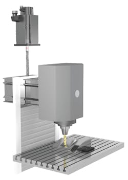
Figure 3: A machining operation was performed to mill an oblique surface on a sample workpiece using differing motor designs for the z axis.
(Source: Heidenhain)
For the comparative measurements used in analyzing the torque ripple of various motor designs, the z axis of the same machine tool under exactly the same test conditions was first moved by an axis motor made for the machine tool and then by an axis motor taken from the automation industry and not specifically designed for the machine tool but rather merely adapted to the particular application. A machining operation was performed to mill an oblique surface on a sample workpiece. During face milling, the z axis was moved at a feed rate of F = 6,250 mm/min for 60 mm in the y direction and for 17.5 mm in the z direction (Figure 3).
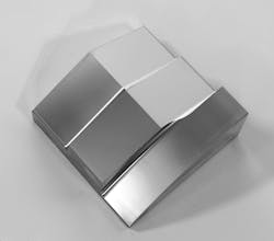
These tests confirm the anticipated effect of the torque ripple, not just by means of the contour error measurement data, the difference between the desired contour and the contour actually milled, but also through the visible effects on the sample workpiece surface (Figure 4). An axis motor that had been optimized for the machine tool features a low torque ripple and generates an evenly angled, machined surface without visible shadings (Figure 5). With the axis motor that had been taken from the automation industry and adapted to the machine tool, the effects of the torque ripple are clearly visible in the form of shadings on the oblique surfaces (Figure 6).
Figure 4: An axis motor with low torque ripple (green line) and the adapted motor with considerably higher deviations (red line) using a 1000x magnification factor for the contour errors.
(Source: Heidenhain)
Expressed in measured values, the low torque ripple axis motor achieved an effective contour error of 0.2 µm at the level of visually discernible deviations. By contrast, the effective deviation of the axis motor adapted to the machine tool came in at 1.2 µm, which is greater by a factor of five.
(Figure 5: The motor designed specifically for the machine tool produced an evenly angled surface without visible shadings.
(Source: Heidenhain)
In order to achieve superior machining results, all the components of the machine tool must be adapted and designed for these special requirements. The same is true of axis motors. Motors made for automation technology tend to be designed with the acceleration capability of the entire system in mind, which is why these motors exhibit the lowest moment of inertia possible relative to their maximum torque. A considerably higher torque ripple is also considered acceptable for these motors. This higher torque ripple manifests itself in the form of visibly inferior surface quality.
Figure 6: The workpiece has clearly visible shadings on the oblique surface after machining with a motor merely adapted to the machine tool.
(Source: Heidenhain)
By contrast, axis motors can be designed specifically for the machine tool and feature not only balanced rigidity and excellent acceleration capability, but also low torque ripple.
ALSO READ: Accurate fishing begins with lights-out manufacturing
Sponsored Recommendations

Leaders relevant to this article:

