Whether you can see them or not, the oscillations from control valves are everywhere in your process. It's just a matter of how large and how important. When the amplitude is less than the exception reporting setting of controllers, data highways and historians, oscillations do a disappearing act on operator displays and trends. This does not mean they are insignificant because the exception reporting (percent change in a process variable that triggers an update) is often set by systems support to minimize traffic and data storage requirements, rather than to show change. Besides, management is much happier when they see straight lines. However, such bliss is short-lived if the hidden cycling translates to product quality or process efficiency issues. So what is the real deal with the source, diagnosis, impact and possible solutions for these oscillations?
Flow Control Troublemakers
The true measure of an automation system is its ability to control change. If there were no load upsets in feed conditions (flow or composition), equipment performance (fouling and efficiency), ambient conditions (temperature and humidity), utilities (temperature and pressure), or changes in set points (due to changes in product demand), we could all retire.
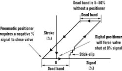
The measurement is the window into the process and the final element is the method of affecting the process. The measurement should provide a fast, undistorted and reproducible view of small changes, and the control valve must be able to make small, rapid changes and not itself be the source of unwanted upsets. In order for a control valve to accomplish its goal, dead band, stick-slip (Figure 1), and, in some cases, stroking time must be minimized.
Dead Band Discussion
Dead band occurs only when the valve needs to change the direction of its stroke. It is measured by how much the signal must change direction to reverse the direction of the stroke. The official test is done for a full-scale stroke in both directions but dead band occurs for any stroke whenever the direction is reversed. It is caused by lost motion and is due mostly to backlash from linkages and actuator shaft and stem connections.
It is worse for rotary valves because of the gaps in rack and pinion gear teeth, the slots in scotch yoke actuators, the key locks in shaft-stem connections, and the linkage that transfers vertical actuator shaft motion to disc, plug or rotary ball movement. A dead band of 8% can be common for such valves even though they are outfitted with digital positioners. More actuator torque does not solve the problem either. The time it takes for the controller output to work through the dead band is dead time that increases the errors from load disturbances.
The problem is not seen for setpoint changes or step changes in the controller output that are much larger than the dead band. Thus, loop analysis or tuning based on large setpoint changes, open-loop step tests or relay methods, will not reveal the additional dead time. For pressure control, it can mean the possible rupture of discs or vessels.
If you consider that the peak error and integrated error for load upsets are proportional to the dead time and dead time squared, respectively, dead band is a hidden menace. There is some consolation, though. For pure dead band, once the valve does move, it then can respond to small changes in signal in the same direction and dead band can cause a limit cycle only in a loop with an integrating response (e.g., level) or a runaway response (an exothermic reactor). A limit cycle is a sustained oscillation of nearly equal amplitude caused by a nonlinear response such as dead band.
Stick and slip occurs whenever the valve needs to move, even in the same direction. After it moves, it cannot move again unless the change in signal is greater than the stick. When it does move, the valve jumps or slips by an amount that usually is larger than the change in signal. Stick and slip generally occur together and have the common cause of friction in the actuator design, stem packing and seating surfaces. Piston actuators, high temperature packing, and tight shutoff in rotary valves (the so-called high-performance valve) can lead to the worst cases of stick-slip. It also can initiate shaft windup, where the actuator shaft moves but the ball, disc or plug does not. It is much worse at positions less than 20% where the ball, disc or plug starts to seat.
Here's the rub: If there is stick-slip, the controller will never get to setpoint, and there will always be a limit cycle. The big squeeze from graphite, environmental packing — particularly when they are tightened — and low-leakage classes are the biggest culprits. A bigger actuator may help, but will not eliminate the problem. An undersized actuator can cause a huge amount of additional slip. Stick-slip of 20% often occurs at breakaway from the seat of high-performance valves and for any valve with Graphoil packing and no positioner. Even with a positioner, a stick-slip of 4% is common with high-friction packing.
Once a valve moves it responds as a velocity-limited exponential. For small changes, the response looks like two time constants in series. For large changes, the response looks like a ramp. Stroking time is a consideration for large actuators and compressor surge or pressure control. The addition of a booster will reduce stroking time, but will introduce a relatively large dead band (e.g., 2%), particularly when designed for piston actuators. The use of a booster without a positioner can cause positive feedback and butterfly disc instability from high outlet-port sensitivity. A booster in series with a positioner must have a bypass around the booster adjusted to prevent a limit cycle.
For most applications, slip is worse than stick, which is worse than dead band, which is worse than stroking time, although none of them are desirable.
Uncover Root Causes
Unless otherwise directed, manufacturers and technicians will make large (10%) signal step changes (much greater than dead band or stick-slip) to their valves at 50% position--far from the seating friction problems. For these tests, the response time is at a minimum and almost any valve looks good.
To make the whole situation even more deceptive, smart digital positioners may give the allusion of good response because they measure actuator shaft position and not actual balance, disc or plug position. You can develop a lot of misleading statistics, diagnostics and trends that are blind to dead band and stick-slip.
A good test should use signal changes that are less than 1%. To test to a rotary valve response in the shop, you need a travel gauge on the ball, disc or plug, since positioner feedback is prone to giving erroneous information. The most positive test is when the valve is in the pipeline at operating conditions, since high temperatures and pressure drops can make stick-slip worse. A sensitive low-noise flow measurement shows whether the ball, disc or plug actually moved.
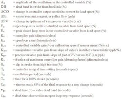
Table I: Know Your NomenclatureA limit cycle in level can be attributed to valve dead band if its amplitude is proportional to the dead band and is inversely proportional to controller gain, and if its period is proportional to the controller integral time and inversely proportional to the square root of the controller gain (The variables are described in Table I):
For stick-slip, the percent amplitude in the controlled variable seen by the controller is proportional to the product of the slip and open-loop gain, which itself is the product of the gains for the manipulated variable, process variable and controlled variable:
The amplitude in the process variable [in engineering units] seen on a trend recording, is without the controlled variable gain factor that is equal to 100% divided by the calibration span. The manipulated variable gain is the slope of the installed characteristic of the control valve.
For oversized valves and steep slopes, the gain is much larger and consequently the effect of slip is much greater. If you also consider that oversized valves tend to ride the seat where the friction is greatest, you get a double hit. Ideally, the amplitude Ao from slip should be less than A/D or D/A resolution, which for a 12-bit microprocessor with one sign bit is 0.05%. This is essentially impossible for oversized valves, small calibration spans, or high process gains.
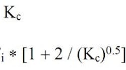
The stick-slip oscillation period depends upon the open-loop gain and the controller settings:
An integral time set too fast for a given valve stroking time can cause an unstable (growing) oscillation for large upsets. The integral time must be larger than the product of the controller gain, the full-scale stroking time, and the open-loop error from a load upset. The loop goes unstable for large load upsets:
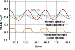
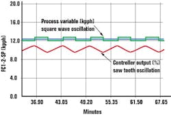
With a little experience, a user can diagnose a limit cycle caused by a control valve. If an integrating process has rounded oscillations in the controlled variable and controller output, but a clipped oscillation in the manipulated flow (Figure 2), it is caused by valve dead band. For dead time-dominant loops, a square wave in the controlled variable and a saw tooth in the controller output (Figure 3) are a sure sign of valve stick-slip.
Calculate the Impact
The additional dead time from valve dead band for load upsets can estimated from:
The peak error in the controlled variable for load upsets is proportional to the ratio of the total loop dead time to the open-loop process time constant:
To estimate the savings from elimination of excess reagent, reactant or reflux flow, the amplitude from Equations 1 or 3 or the peak error from Equation 8 is divided by the product of the gains of the process variable and controlled variable to get back to the change in flow:
For back mixed volumes, the amplitude of the oscillation in the reagent flow should be multiplied by process gain and an amplitude ratio from frequency response that is proportional to loop oscillation period and inversely proportional to the mixing time constant to get a filtered amplitude of oscillations in a key process variable of interest:
The process gains in Equations 9 and 10 are different for different process variables or for processes with operating point nonlinearities (e.g., pH). The elimination of the oscillation in the process variable can translate to a proportional shift to a more optimum set point or a reduction in scrap or downgraded product.
[sidebar id="4"]
Solution in the Selection
Control valves designed for on-off operation generally are a poor choice for a control valve. Conversely, throttling valves should not be used for isolation or interlocks.
A calculation can be made to compensate for backlash by adding a bias to the controller output whenever a signal reversal exceeds a noise band. However, the exact dead band is a moving target and a bias greater than the actual dead band effectively creates slip. Also, stick-slip goes hand-in-hand with dead band in high-performance valves.
The control valve that responds best to small changes is a judiciously sized sliding stem (globe) valve with a digital positioner and a correctly sized diaphragm actuator and properly tightened Teflon packing. It has negligible backlash and a stick-slip of 0.1%. If you must use a rotary valve, avoid tight shutoff and high-friction packing and use a diaphragm actuator with a short shaft and splined connections between the actuator shaft and the ball, disc or plug stem. Make sure the ball, disc or plug are cast with its stem otherwise the junction between the ball, disc or plug and its stem can become another source of backlash. If high temperature or environmental packing must be used, increase the actuator size and positioner gain to help it better deal with the packing's increased friction.
|
Big Problems for Small Valves Small valves are more prone to improper sizing, irregular flow characteristics, greater stick-slip and plugging. Here, size does matter because most of these problems originate from extremely small Reynolds Numbers, clearances, and stem diameters. For a CV less than 0.01 or extremely viscous fluids, the valve may be operating in the laminar flow regime or in the region of transition from turbulent to laminar flow. Liquid flow moves from being approximately proportional to the square root of the pressure drop towards being proportional to the pressure drop as the flow goes from being fully turbulent to completely laminar. For anything other than a 1-psi pressure drop this can translate to an enormous sizing error. The result is often an oversized valve that rides the seat, where the high seating friction causes excessive stick-slip. Even worse, operation in the transition region where the flow for a particular valve position has poor reproducibility, because normally insignificant disturbances such as microscopic changes in roughness or small vibrations can trigger a switch between turbulent and laminar flow and an erratic installed flow characteristic. If you also consider the possibility of a significant distortion of the inherent flow characteristic caused by machining tolerances that are an appreciable portion of the clearances for such tiny trim sizes, the scene is set up for an unknown and extreme nonlinearity. Tiny clearances can pose all sorts of problems because small particles and coatings cause plugging and sticking. The low flow velocities at the surface that is normally associated with laminar flow makes the likely hood of coating much greater. Finally, tiny stems are likely to be bent from normal handling both before and after installation. Slight deflections of the stem can cause huge amounts of stick-slip. What good is a control valve if you can't drop it or step on it? Is the situation hopeless? Not if you go with a manufacturer who specializes in tighter machining tolerances and minimizing stick-slip. I would stay away from stems smaller than 3/8 inch and I would insist on getting response and flow test results. I would use computer programs now available that properly deal with laminar flow and offer an installed characteristic curve for your piping and operating conditions. Even though a smart digital positioner may be larger and cost more than the valve, it is more important than ever that it be used and properly tuned for the small actuator volume. The challenge here is for packaged platforms that are going for low bid not to get cheap where it hurts. If there is a tendency for plugging, pulse-width modulation is a solution if there is sufficient back-missed volumes to attenuate the pulses. This also can provide a linear flow characteristic and a flow large enough to be turbulent. The ratio of maximum to minimum pulse width establishes the rangeability. The maximum pulse width, and hence, cycle time determine the degree of variability that needs to be filtered and the additional dead time from the pulse off time. Now stroking time can be an issue because it is desirable to have the minimum pulse be as short as possible. |
A variable-speed drive is another possible solution, but the user needs to be aware of a dead band that is artificially introduced into the electronics and the minimum discharge head requirements to prevent reverse flow for varying static heads.
Interestingly enough, valve specifications do not require that a control valve move. A response requirement should be added to the control valve specification that details the stick-slip, dead band, and the response time (63) for a small step in the throttle range. Ideally, a ramp at the expected rate of change of the loop should be used rather than a step, to reveal the hidden dead time from dead band and the saw tooth from stick-slip.
Sponsored Recommendations

Leaders relevant to this article:
